Page 38
Bradford White Corp
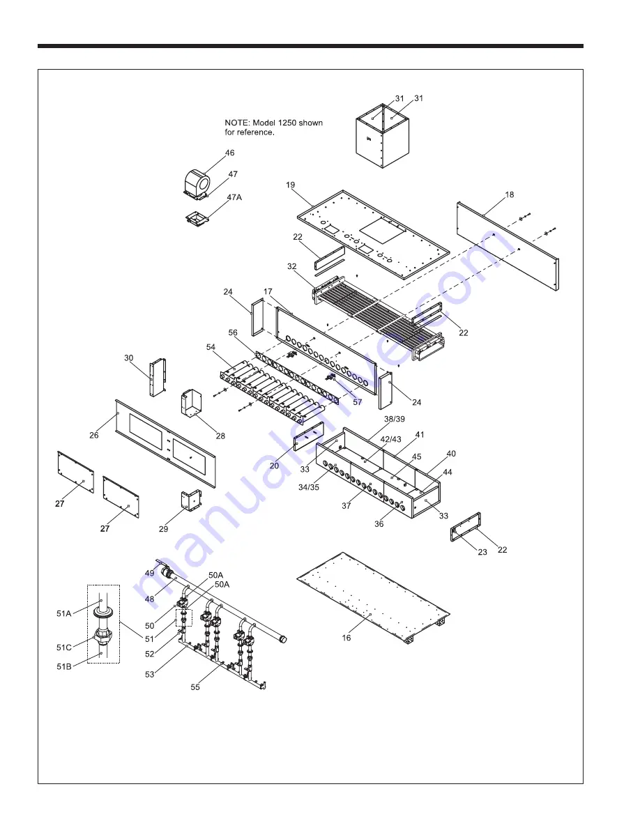
Figure 24. Internal Components
Page 1: ...r d essence ni d autres vapeurs ou liquides inflammables dans le voisinage de cet appareil ou de tout autre appareil QUE FAIRE SI VOUS SENTEZ UNE ODEUR DE GAZ Ne pas tenter d allumer d appareils Ne to...
Page 2: ...Heaters 4B 1 Water System Piping Water Heater 14 4B 2 Hot Water Supply Piping Water Heater 15 4B 3 Water Flow Requirements Water Heater 15 4B 4 Combined Water Heating potable and Space Heating Water H...
Page 3: ...White factory or local factory representative with any issues or questions regarding this equipment Experience has shown that most operating issues are caused by improper installation The Brute Delux...
Page 4: ...ry items are shipped in separate packages Verify receipt of all packages listed on the packing slip Inspect everything for damage immediately upon delivery and advise the carrier of any shortages or d...
Page 5: ...ump is sized for 30 feet 9 1m of piping If the appliance must be installed with longer piping runs then larger diameter pipe or tubing shall be used Consult the factory for assistance Figure 1 Dimensi...
Page 6: ...gure 2 Dimensional Data pump mounted models HORIZONTAL INTAKE AIR VENT COLLAR VENT PIPE PIPE MAX PIPE MAX NO SIDE WALL SIDE WALL SIZE SIZE DIAMETER DIAMETER LENGTH OF ELBOWS VENT COMBUSTION TERMINAL A...
Page 7: ...ings shall communicate directly or by ducts with the outdoors or spaces that freely communicate with the outdoors When directly communicating with the outdoors or when communicating to the outdoors th...
Page 8: ...he vent system must conform to the National Fuel Gas Code ANSI Z223 1 Latest Edition in the U S or in Canada to CSA B149 1 latest edition The vent system must be sized and installed for a Category I F...
Page 9: ...appliances with condensing vents are not permitted to terminate above a public walkway or over an area where condensate or vapor could create a nuisance or hazard 3 Locate the vent terminal so that v...
Page 10: ...t 3 feet 91 cm above if within 10 feet 3 m 6 feet 1 83 m horizontally Vent termination not allowed in this location Vent termination not allowed in this location for category IV appliances A vent shal...
Page 11: ...ight 8 feet above grade directly in line with the exhaust vent terminal for the horizontally vented gas fueled heating appliance or equipment The sign shall read in print size no less than one half in...
Page 12: ...fans such as range hoods and bathroom exhausts so they will operate at maximum speed Do not operate a summer exhaust fan Close fireplace dampers 4 Place in operation the appliance being inspected Foll...
Page 13: ...ring any pressure testing of that system at test pressures in excess of 1 2 PSIG 3 45kpa 9 The unit must be isolated from the gas supply system by closing its individual manual shutoff valve during an...
Page 14: ...he system To ensure a proper operating temperature leading to long boiler life a flow rate has been established based on the fluid temperature rise for this specific size boiler Pump mounted boilers c...
Page 15: ...including copper if the water is moved too quickly The water flow requirements for the Brute Deluxe water heater are based upon the hardness of the water The water flow is kept high enough to prevent...
Page 16: ...Page 16 Bradford White Corp Figure 6 Hydronic Piping Multiple Boilers Primary Secondary System Figure 7 Hydronic Piping Multiple Boilers Low Temperature System...
Page 17: ...Page 17 Brute Deluxe 500 2000 Install Operating Figure 8 Hydronic Piping One Boiler Multi Temperature System Figure 9 Hydronic Piping Primary Secondary Reverse Return...
Page 18: ...Page 18 Bradford White Corp Figure 10 Hydronic Piping Primary Secondary Reverse Return Low Temperature Figure 11 Water Heater Piping One Heater One Tank...
Page 19: ...Page 19 Brute Deluxe 500 2000 Install Operating Figure 12 Water Heater Piping Multiple Heaters One Tank Figure 13 Water Heater Piping One Heater Multiple Tanks...
Page 20: ...19 170 257 341 0 6 1 1 1 9 21 14 10 1250 68 68 90 3 8 3 8 6 3 31 31 24 257 257 341 1 2 1 2 1 9 17 17 13 1500 68 68 90 3 9 3 9 6 5 38 38 28 257 257 341 1 2 1 2 2 0 21 21 16 1750 68 68 90 4 0 4 0 6 7 4...
Page 21: ...rk on or around the boiler may be standing on wet floors and could be electrocuted by an ungrounded boiler Single pole switches including those of safety controls and protective devices must not be wi...
Page 22: ...BLOWER 1 LOW HIGH LOW HIGH K1 K2 K1 K2 F2 35 67 F2 35 67 F1 35 67 F1 35 67 K3 HSI 2 HSI 1 120 VAC DPDT MAIN POWER SWITCH S2 S2 35 67 35 67 L2 35 67 L2 35 67 BD 1 IGN S1 S1 35 67 35 67 35 67 L1 35 67 J...
Page 23: ...Page 23 Brute Deluxe 500 2000 Install Operating Figure 19 Brute Deluxe 500 750 Connection Diagram...
Page 24: ...Page 24 Bradford White Corp Figure 20 Brute Deluxe 1000 Connection Diagram...
Page 25: ...K W L2 LOAD 1 1 2 3 4 5 6 7 8 9 10 10 lockout indicator T stat lockout indicator G Pressure Switch Gas Valve 24V Ground Remote Sense S1 L1 L2 S2 Fenwal F1 F2 lockout indicator T stat lockout indicator...
Page 26: ...tiple boiler control BAS etc wire Stage 1 to the terminals marked Input Stage 1 and Stage 1 and wire Stage 2 to the terminals marked Input Stage 2 and Stage 2 The Local Remote selector switch above th...
Page 27: ...ll bleeding devices and open make up water valve Allow system to fill slowly 2 If make up water pump is employed adjust pressure switch on pumping system to provide a minimum of 12 psi 81 8 kPa at the...
Page 28: ...but with differing reductions in output At elevations higher than 7700 ft 2347 m the reduction in output will exceed 10 and at elevations below 7700 ft 2347 m it will be less than 10 High altitude adj...
Page 29: ...ist in these adjustments are a CO2 or O2 Analyzer and a U Tube Manometer or other device capable of reading a pressure of 2 5 3 0 inches W C 0 62 0 75 kPa Start the adjustment process by checking the...
Page 30: ...ore and after the valve and remove the valve Re install in reverse order Ensure o rings are properly installed for both inlet and outlet Turn on manual gas shutoff valve and 120 volt power and check a...
Page 31: ...al gas valve on the heater 3 Disconnect and remove the wires conduit and sensors from all components that are attached to the inlet outlet header 4 Isolate the heat exchanger from the water supply 5 D...
Page 32: ...esentative to discuss possible remedies 8 4 Short Cycling Water Heater Short cycling will generally occur only in combination space heating and water heating applications when the water heater is oper...
Page 33: ...F3015 5F3015 5F3015 13 Cover Housing Pump 5F3016 5F3016 5F3016 5F3016 5F3016 5F3016 5F3016 14 Cover Pipe Gas Manifold 5F3304 5F3304 10F3304 20F3304 20F3304 20F3304 20F3304 2 2 2 2 2 2 2 Internal Compo...
Page 34: ...2018000 T2017400 T2018000 T2017400 45 Tile Bottom Center T2015900 T2015900 T2015900 T2015900 1 1 2 2 Gas Train Components See Figure 24 46 Blower A2111900 A2111900 A2111900 A2111900 A2111900 A2111900...
Page 35: ...59 Low Water Cutoff optional E2076500 E2076500 E2076500 E2076500 E2076500 E2076500 E2076500 60 Gauge Temperature Pressure A0079000 A0079000 A0079000 A0079000 A0079000 A0079000 A0079000 62 Tee Adapter...
Page 36: ...E0093200 E0093200 E0093200 79 Panel Mounting Limits Ignition Control 5F7001 5F7001 5F7001 5F7001 5F7001 5F7001 5F7001 80 Panel Cover High Limit Ignition Control 5F7003 5F7003 5F7003 5F7003 5F7003 5F70...
Page 37: ...Page 37 Brute Deluxe 500 2000 Install Operating Figure 23 Sheet Metal Components...
Page 38: ...Page 38 Bradford White Corp Figure 24 Internal Components...
Page 39: ...001800 1250 A2001800 1500 A2001900 1750 A2001900 2000 A2109700 Brute Deluxe Water Heater Size Pump p n Soft Water Normal Water Hard Water 500 A2001700 A2001700 A2001900 750 A2001700 A2001700 A2001900...
Page 40: ...Bradford White Corporation reserves the right to change specifications components features or to discontinue products without notice 200 Lafayette St Middleville MI 49333 Warranty 800 531 2111 www Br...