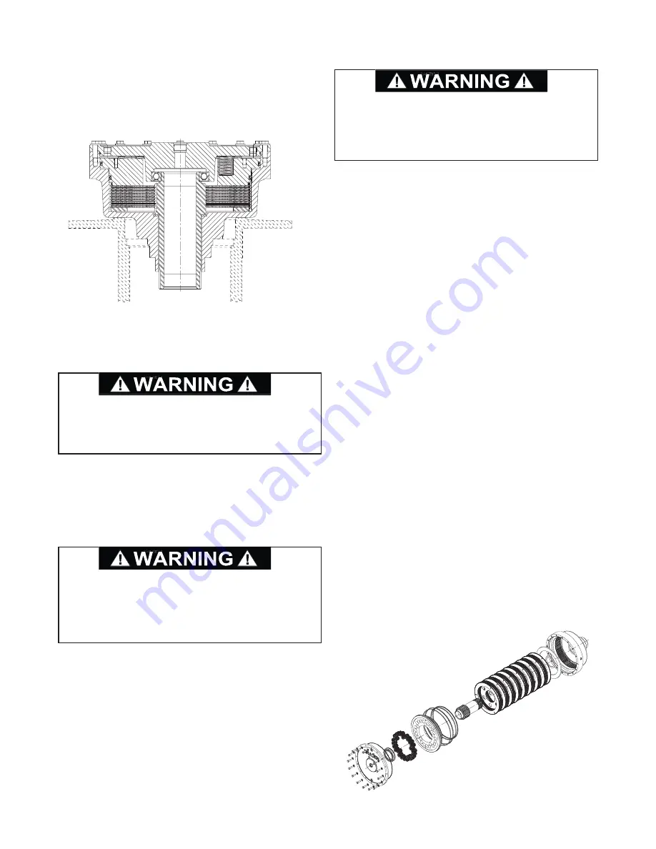
1. Carefully turn the auxiliary brake assembly over and
place it with the end cover facing upward. Use the
proper precautions to keep from damaging the bear-
ing and seal surfaces at the end of the brake hous-
ing.
NOTE:
Place the cable drum on the floor with the
motor end facing up. This will provide a stable plat-
form in which to locate the auxiliary brake assembly
to allow proper servicing.
2. Carefully loosen the capscrews in a slow, alternat-
ing manner to remove the spring force on the brake
housing cover. Remove the brake housing cover
and discard the o-ring. The ball bearing at the end
of the brake shaft may come out with the cover.
Take care to not drop it.
3. Remove the brake springs. Inspect the springs for
damage or deformation. Check the spring free
length which should be no less than 1.938 in. (49
mm). If any spring is damaged or of incorrect length,
replace ALL springs.
4. Using 3/8-16 UNC eyebolts inserted in the lifting
holes, lift the piston out of the housing. Tap the
edges of the housing with a soft hammer to break
the suction and relieve the seal drag between the
piston and housing.
5. Remove and discard the o-rings and back-up rings
from the piston. Inspect the piston groves for
scratches, burrs or other damage.
6. Remove the brake plates, friction discs and spacer
from the housing.
7. Lay the friction plates on a clean, flat surface and
check for distortion or warpage. The friction sur-
faces should be well defined with visible oil grooves.
The splines should be uniform and square-ended. If
they are worn to a point, they should be replaced.
8. Inspect the steel brake plates in the same manner
as the friction plates. Check for distortion, warpage
or discoloration indicating excessive heat. Replace
as required.
9. Remove the brake shaft and thrust washer. Inspect
the bearing surfaces of the brake shaft for wear or
damage. Inspect the splines at both ends of the
shaft for burrs or other damage. The large splines
should have no indentions that would impair the
ability of the brake plates to slide smoothly during
brake release. Ensure the thrust washer is smooth
and flat.
10. Inspect the splines in the brake housing to ensure
there are no indentions can cause the brake plates
to hang up in operation, impairing their ability to
slide during brake release. Also, ensure the oil pas-
sage is clear of obstructions and the sealing sur-
faces are not scratched or otherwise damaged.
AUXILIARY BRAKE SERVICE
40
The auxiliary brake assembly weighs approximately
390 lbs (177 kg). Use the proper precautions when
handling these parts to eliminate the possibility of
component damage or personal injury.
The brake housing cover is under direct spring force
of approximately 2,000 lbs (907 kg). Use extreme
caution when removing the cover capscrews. Use of
careless or improper disassembly methods can
result in severe injury or death.
The brake piston weighs approximately 78 lbs (35
kg). Use the proper precautions when handling these
parts to eliminate the possibility of component dam-
age or personal injury.
AUXILIARY BRAKE ASSEMBLY


