


ENGLISH-12
ENGLISH-12
O
O
O
O
P
P
P
P
E
E
E
E
R
R
R
R
A
A
A
A
T
T
T
T
II
II
O
O
O
O
N
N
N
N
S
S
S
S
((
((
c
c
c
c
o
o
o
o
n
n
n
n
tt
tt
ii
ii
n
n
n
n
u
u
u
u
e
e
e
e
d
d
d
d
))
))
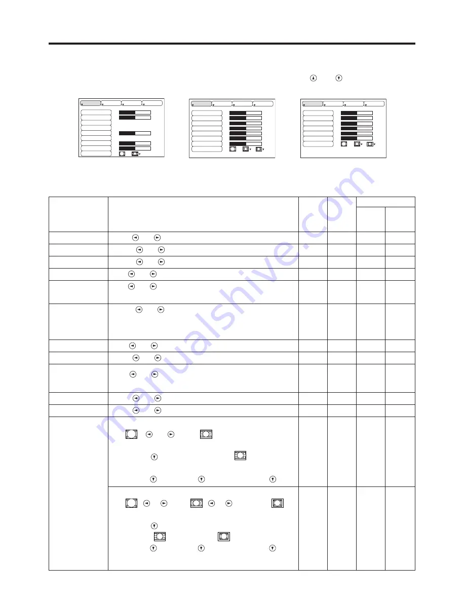
Setup Menu
The following adjustments and settings are possible when SETUP is selected at the top of the menu. Part of the
Setup menu differs between RGB input and video input. Select an item with the
and
buttons, and start
operation. Use the Single menu to reduce menu size (see Table 3, MENU SELECT).
VIDEO/S-VIDEO
COMPONENT
RGB
BRIGHT
CONTRAST
V POSIT
H POSIT
H PHASE
H SIZE
COLOR BAL R
COLOR BAL B
ASPECT
0
-2
+1
0
0
100
100
800
SETUP
INPUT
OPT.
IMAGE
BRIGHT
CONTRAST
SHARPNESS
COLOR
TINT
COLOR BAL R
COLOR BAL B
ASPECT
0
+1
+1
0
0
0
0
SETUP
INPUT
OPT.
IMAGE
BRIGHT
CONTRAST
COLOR
H PHASE
COLOR BAL R
COLOR BAL B
ASPECT
0
+1
+1
0
0
0
SETUP
INPUT
OPT.
IMAGE
Table 4. Setup Menu
Item
Description
RGB
VIDEO
S-VIDEO
COMPONENT
480i
575i
480P
720P
1080i
BRIGHT
Dark
↔
Light
✔
✔
✔
✔
CONTRAST
Weak
↔
Strong
✔
✔
✔
✔
V POSIT
Down
↔
Up
✔
-
-
-
H POSIT
Left
↔
Right
✔
-
-
-
H PHASE
Left
↔
Right
• Adjust to eliminate flicker.
✔
-
✔
✔
H SIZE
Small
↔
Large
• The image may not be displayed correctly if the horizontal
size is excessive. In such cases, press the RESET button,
and initialize the horizontal size.
✔
-
-
-
SHARPNESS
Soft
↔
Clear
-
✔
-
-
COLOR
Light
↔
Dark
-
✔
✔
✔
TINT
Red
↔
Green
• Valid only when NTSC or NTSC 4.43 signal is received.
-
✔
-
-
COLOR BAL R
Light
↔
Dark
✔
✔
✔
✔
COLOR BAL B
Light
↔
Dark
✔
✔
✔
✔
ASPECT
Select Image Aspect Ratio :
4:3[
]
↔
16:9[
]
Select Position of Image:
Press the
button while 16:9[
] is
selected.
Center
→
Down
→
Up (
→
Center )
✔
-
-
✔
Select Image Aspect Ratio:
4:3[
]
↔
16:9[
]
↔
4:3small[
]
Select Position of Image :
Press the
button
while 16:9[
] / 4:3 small[
] is selected.
Center
→
Down
→
Up (
→
Center )
• 4:3 small may not be displayed correctly with some input
signals.
-
✔
✔
-
Summary of Contents for CP-635i
Page 26: ...Printed in Japan QR53221...


