


Item
Description
VOLUME
Volume Adjustment :
Press the VOLUME
/
button.
MUTE
Set/Clear Mute Mode :
Press the MUTE button. No sound is heard in the
MUTE mode.
AUTO
Automatic Adjustment at RGB Input :
Press the AUTO button. Horizontal
position(H.POSIT), vertical position (V.POSIT),clock phase (H.PHASE), and
horizontal size(H.SIZE) are automatically adjusted. Use with the window at
maximum size in the application display.
Automatic Adjustment at Video Input :
Press the AUTO button. A signal
type appropriate for the input signal is selected automatically. Valid only
when AUTO is set for VIDEO on the menu.
• This operation requires approximately 10 seconds. It may not function correctly with
some input signals.
BLANK
ON/OFF
Set/Clear Blank Mode:
Press the BLANK button. No image is displayed in
the Blank mode. The screen color is as set in BLANK on the Image menu.
MENU
ON/OFF (
*)
Menu Display Start/Stop:
Press the MENU button.
• The menu display is terminated automatically after approximately 10 seconds of
inactivity.
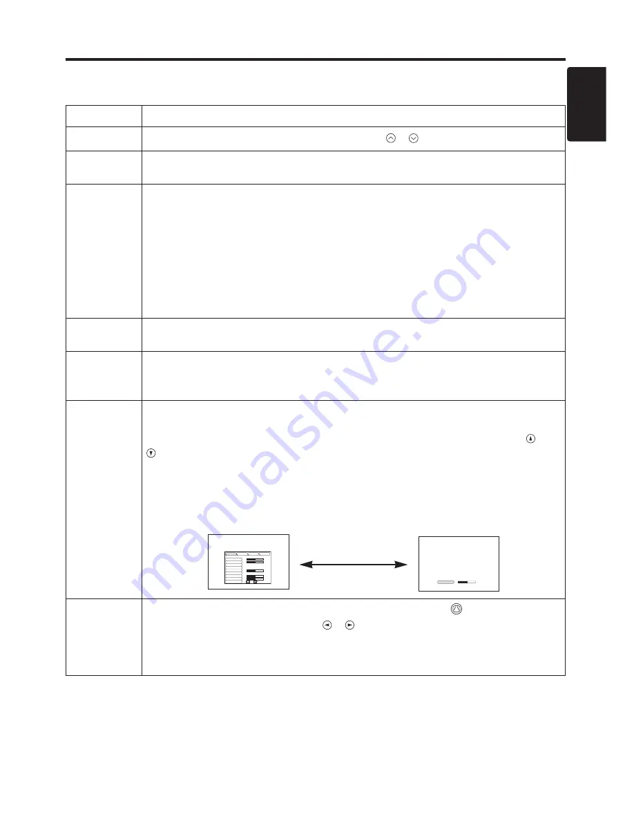
MENU
SELECT
Select Menu Type:
Press the MENU SELECT button. Allows the user to
select the normal menu or the single menu. Only the selected item is
displayed on the single menu, and other items are displayed with the
and
buttons as with the normal menu.
• Valid only when the Setup menu is used. Push the MENU SELECT button after
selecting items such as "BRIGHTNESS".
• The MENU SELECT button may operate as the mouse control button. Refer to
page 4.
Normal menu
Single menu
KEYSTONE
(
*)
Set / Clear KEYSTONE Mode :
Press the KEYSTONE
button.
Adjust KEYSTONE :
Press
the / button.
• The image may not be appeared properly when this function is activated on same
input signals.
• The adjustable range of distortion correction will be different among input signals.
ENGLISH-11
ENGLISH
ENGLISH-11
O
O
O
O
P
P
P
P
E
E
E
E
R
R
R
R
A
A
A
A
T
T
T
T
II
II
O
O
O
O
N
N
N
N
S
S
S
S
((
((
c
c
c
c
o
o
o
o
n
n
n
n
tt
tt
ii
ii
n
n
n
n
u
u
u
u
e
e
e
e
d
d
d
d
))
))
Items indicated by (*) may be used from the control panel.
Table 3. Basic Operation (continued)
CONTRAST
-2
BRIGHT
CONTRAST
V POSIT
H POSIT
H PHASE
H SIZE
COLOR BAL R
COLOR BAL B
ASPECT
0
-2
+1
0
0
100
100
800
SETUP
INPUT
OPT.
IMAGE
(MENU SELECT)
Summary of Contents for CP-635i
Page 26: ...Printed in Japan QR53221...


