Boston Gear • 800-825-6544
P-3002-BG
9
Note:
The Type “N” and “R” coupling connection
is rigid and does not allow for forgiveness
of parallel or angular misalignment. To
eliminate unnecessary bearing loads, both
shafts must be in near perfect alignment.
8. Loosen the coupling setscrews and attach
coupling to clutch with hex head bolts and flat
washers. Refer to Table 10 for recommended
bolt seating torques. Secure coupling to drive
shaft by tightening the setscrews. (Refer to
Table 8)
IV. Limit Switches
Figure 13 shows a typical use of a limit switch to
detect an overload condition. The switch should be
able to operate within the travel of the limit switch
plate. Upon overload, the limit switch plate will
move to actuate the limit switch and shut down the
drive.
The switch should be wired in parallel with a jog
circuit so that the drive can be indexed for
re-engagement. After the clutch has been
re-engaged, the limit switch will be reset and the
drive can be restarted.
V. General Maintenance
A. Lubrication
The ORC Series, Model F Overload Release
Clutch is prelubricated at the factory and is also
equipped with a grease pack fitting. For optimum
performance and wear resistance it is suggested
that the clutch be lubricated with a Bentone type,
NLGI grade 0 grease. The lubrication schedule
should be in accordance with good operating
practices for the equipment on which the clutch is
mounted. The clutch is also supplied with a grease
relief fitting. When there is enough grease in the
clutch any excess grease will be extruded through
the relief fitting.
B. Annual Inspection
The ORC Series, Model F Overload Release Clutch
is constructed of heavy duty materials. Under
reasonably clean conditions the unit will operate
with a minimum of maintenance. A scheduled
annual inspection of bearings, pawls, rotor, springs,
actuating plate, cam plate and other internal
components is suggested. However, the actual
frequency should be in accordance with good
operating practices for the equipment on which the
clutch is installed.
VI. Repair Instructions
A. General Disassembly
1. All item numbers in parenthesis will refer
to clutch exploded view drawing and parts
identification table.
2. Place the clutch preferable in a three-jaw chuck
with the actuating plate facing up.
3. Remove the return pin nuts (32) from the return
pins. This is accomplished by holding the return
pin steady with a screwdriver while turning the
return pin nut counter-clockwise with a box or
open end wrench.
4. Lift off the actuating plate (26) from the clutch.
5. There are two locking screws (24) located on
the face of the cover which lock down the reset
spring screw (15) and the drive spring screw
(20). Loosen these screws to relive the pressure
on the drive spring screw and reset spring
screw.
6. Turn the reset spring screw (15) counter-
clockwise to relieve the compression on the
reset spring (18).
7. Remove the sealing wax from the drive spring
screw (20) and turn the screw counterclockwise
to relieve the compression on the drive spring
(17).
8. Remove the cam plate (36) from the face of the
cover (8). Be sure not to pry on the outer edge
of the cover as the outer lip may break. (See
Figure 14)
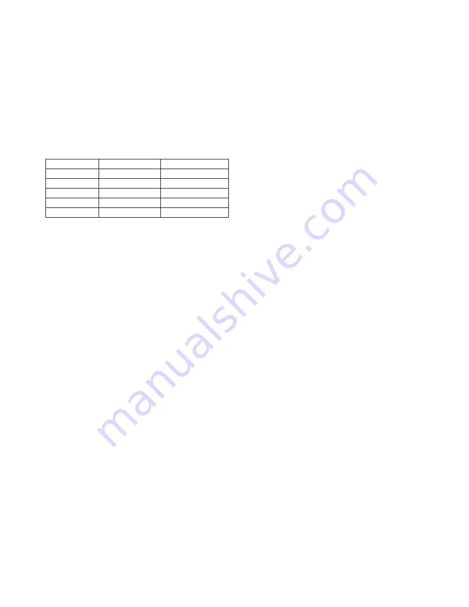
Size
Bolt Size
Seating Torque
1
5/16-18
170 in.lb.
2
3/8-16
300 in.lb.
3
1/2-13
750 in.lb.
4
5/8-11
1,270 in.lb.
5
5/8-11
1,270 in.lb.
Table 10 - Coupling Mounting Bolt Seating
Torques


