12
Boston Gear • 800-825-6544
P-3002-BG
3. If the unit is a Model FJ or FG, place the locking
collar (13) onto the sawcut section of the rotor
and tighten. If the clutch is a Model FR, remove
the access screw from the hole stamped 22 on
the housing. Insert hex wrench through this hole
and tighten the rotor setscrew. Replace the
access screw.
4. Turn the drive spring screw (20) clockwise until
it is flush with the surface of the housing. (See
Figure 15)
5. The clutch is supplied with a torque selector
dial. The torque selector dial is the two or three
mill marks located at the hole stamped 9 on the
housing. If a drive spring (17), reset spring (18),
and/or a reset spring screw (15) were replaced,
chances are that the stamped torque values on
the dial are no longer valid. It may be necessary
to grind the old numbers off and to stamp new
numbers.
6. Tighten the reset spring screw (15) until it
reaches the limit stop pin (4). this will be the
maximum torque position. If the maximum
torque is not desired, tighten the reset spring
screw to one of the locations on the torque
selector dial.
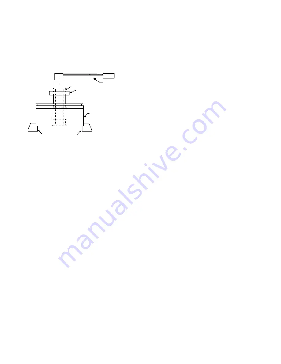
7. Disengage the clutch with a torque wrench.
Fine tune the torque by turning the drive spring
screw (20) until the desired release torque is
obtained.
8. Once the desired release torque is obtained,
tighten the locking screws (24) located over the
drive spring and reset spring screws to ensure
that they will not move.
D. Final Assembly
1. Remove the torque wrench, locking collar
(for Model FJ and FG), and arbor. For Model
FR, remove the access screw from the hole
stamped 22 on the housing, loosen the rotor
setscrew and replace access screw. Then
remove the clutch from chuck or vise.
2. Apply a thin coat of grease to the “O”-ring (39)
and place it into groove on the outer edge of
the cover. Be sure not to twist the “O”-ring.
3. Insert the Woodruff key (37) into the keyslot
of the rotor. The Woodruff key may require a
gentle tap with a hammer.
4. Press the cam plate (36) onto the rotor.
5. Place the actuating plate (26) over the rotor and
cover. There is an arrow on the actuating plate
which should point to the keyway in the rotor
when properly installed. The return pins should
fit through the proper holes in the actuating
plate. (See Figure 17)
6. Install the return pin nuts (32) onto the end of
the return pins. This is accomplished by holding
the return pin steady with a screwdriver while
turning the return pin nut clockwise with a box
or open end wrench.
7. If the clutch is a Model FJ or FG, install the
locking collar (13) onto the sawcut section of
the rotor. Do not tighten the collar until the
clutch is installed on the shaft. Refer to Section
III for installation of the basic clutch.
E. Limit Switch Actuating Plate Assembly
(Sizes 1 and 5)
1. Push liftout buttons (27) through appropriate
holes in the actuating plate (26). Secure each
liftout button with a snap ring (28).
2. Push holdout buttons (29) through appropriate
holes in the actuating plate (26). Secure each
holdout button with a snap ring (30).
Model F Clutch
Vice or Chuck Jaws
Collar
Arbor
Torque Wrench
Figure 16


