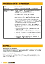
BossWeld Buddy MIG 150 Instruction Manual Download Page 13

13

bossweld

.com.au

Problem

Suggested Remedy

Power indicator is not lit, 

fan does not work and 

no output current

1.  Check that the welder is plugged into the 240V mains outlet and is 

switched on.

2. Check that the mains fuse or breaker has not operated.
3. Check that the main switch on the rear of the unit is in the on position.

Power indicator is lit, fan 

works, no output current

1. Check the welding cables are connected correctly.  
2. Check the output connectors are not disconnected or damaged.
3.  Check that the work clamp is connected securely to the work piece 

and that the contact point is clean of paint or rust.

Over temperature indicator 

is on, no output current

1.  Duty cycle of the unit has been exceeded.  Allow the unit to cool.

Output current is not 

stable.

1. Check mains voltage is constant.
2. Check the welding cable connectors are tight in the sockets.
3. Check the work clamp connection to the work piece.
4. Check the welding leads are not reversed.

Excessive Spatter

1.  Check that the output polarity is correct for the type of electrode or 

wire being used

Porosity 

(Small cavities or holes 

resulting from gas 

pockets in weld metal)

1. Check that the correct gas is being used
2.  Check the gas is connected; check hoses, gas valve and torch are 

not restricted and free of leaks. Set the gas flow between 10 - 15 l/

min flow rate. Protect the welding zone from wind and drafts

3. Remove all moisture from base metal before welding
4.  Remove materials like paint, grease, oil, and dirt, including mill 

scale from base metal

5.  Use clean dry rust free wire. Do not lubricate the wire with oil, 

grease etc.

6.  Check and tighten connection.
7. Clean or replace the gas nozzle
8. Replace the gas diffuser

Wire stubbing during  

welding

1.  Bring the torch closer to the work and maintain stick out of 

5-10mm

2. Increase the voltage
3. Decrease the wire feed speed

Lack of Fusion − failure 

of weld metal to fuse  

completely with base 

metal or a proceeding 

weld bead

1.  Remove materials (paint, grease, oil, dirt, mill scale) from base metal
2. Select a higher voltage range  and /or adjust the wire speed to suit
3.  Keep the arc at the leading edge of the weld pool. Torch angle to 

work should be between 5 & 15° Direct the arc at the weld joint

4.  Adjust work angle or widen groove to access bottom during welding, 

Momentarily hold arc on side walls if using weaving technique

5.  Select a lower voltage range  and /or adjust the wire speed to suit 

Increase travel speed

Lack of Penetration

1.  Select a higher voltage range  and /or adjust the wire speed to suit 

Reduce travel speed

2.  Remove materials like paint, grease, oil, and dirt, including mill 

scale from base metal

TROUBLE SHOOTING

Summary of Contents for Buddy MIG 150

Page 1: ...1 bossweld com au INSTRUCTION MANUAL MIG 150 MIG STICK ...

Page 2: ...ooting Page 13 Trouble Shooting Wire Feeder Page 14 Disposal Page 14 Box Contents Page 15 Optional Accessories Page 15 Warranty Information Page 16 SPECIFICATIONS Power Supply Primary Input Plug Fitted Duty Cycle Open Circuit Voltage Output Current Range I ieff Input Current Max Protection Class MIG Wire Range Electrode Diameter Range Thermal Overload Protection Machine Dimensions Machine Weight 2...

Page 3: ... Voltage 3 Digital Display Amperage 4 Manual MIG Mode Indicator Light 5 Synergic MIG Mode Indicator Light 6 Stick Mode Indicator Light 7 VRD Indicator Light Indicates that the Voltage Reduction Device is operating VRD reduces the Open Circuit Voltage before welding for added safety 8 Process Selection Button 9 Voltage Parameter Adjustment Knob L 10 Current Wire Speed Parameter Adjustment Knob R 1 ...

Page 4: ...are not familiar with this user guide should not use this welder Keep this booklet in a safe place for future reference TRAINING The operator should be properly trained to use the welding machine safely and should be informed about the risks relating to arc welding procedures This user guide does not attempt to cover welding technique Training should be sought from qualified experienced personnel ...

Page 5: ...ld flammable liquids or combustible gases or pressure Do not weld on coated painted or varnished surfaces as the coatings may ignite or can give off dangerous fumes WORK PIECE When welding the work piece will remain at high temperature for a relatively long period The operator must not touch the weld or the work piece unless wearing welding gloves Always use pliers or tongs Never touch the welded ...

Page 6: ...ag from the weld OTHER PERSONS Ensure that other persons are screened from the welding arc and are at least 15 metres away from the work piece Always ensure that the welding arc is screened from onlookers Use screens if necessary or non reflecting welding curtain Do not allow children or animals access to the welding equipment or to the work area SWITCHING OFF When the operator has finished weldin...

Page 7: ... wire size used 6 Carefully feed wire through the inlet guide tube on to the drive roller and into the outlet guide tube until it passes through the Inlet Tube and into the torch Note Hold wire to prevent the spool uncoiling 7 Close the Wire Feed Tension Arm Replace Wire Feed Tension Adjustment Knob and tighten Do not overtighten Set Up MIG Torch 8 Remove the nozzle and the welding tip from the to...

Page 8: ...urn on the machine using the power switch on the rear of the machine 6 Select MIG welding mode by pressing the Welding Process Selection Button until the MIG Welding Process Indicator Light is illuminated 7 MIG Manual Mode Adjust the Voltage Knob L and Current Wire Feed Speed Knob R to obtain the desired settings 8 MIG Synergic Mode Adjust the Current Wire Feed Speed Knob R and the Voltage setting...

Page 9: ...s good contact with bare metal 6 Plug the machine 10Amp input power lead into the wall socket ensuring that the power switch on the machine is in the OFF position 7 Turn the power outlet on and turn on the machine using the power switch on the rear of the machine 8 Carefully open the valve of the gas cylinder Adjust to required gas flow rate as indicated on the regulator As a guide start with a ga...

Page 10: ... torch at an angle of approximately 10 Note Different angles will result in different weld bead shapes 2 Pull the trigger and slowly push the MIG torch away from you in the direction you wish to weld ensuring the wire is pointing forward towards the leading edge of the weld Backhand Pulling Technique 1 Hold the MIG torch at an angle of approximately 10 Note Different angles will result in differen...

Page 11: ... to clamp the electrode Welding Setup 5 Plug the machine 10Amp input power lead into the wall socket ensuring that the power switch on the machine is in the OFF position 6 Turn the power outlet on and turn on the machine on using the power switch on the rear of the machine WARNING Ensure the electrode electrode holder is not near the work piece when switching on the machine 7 Select MMA welding mo...

Page 12: ...mps 3 2mm 105 140 Amps 4 0mm 140 160 Amps WARNING Ensure appropriate PPE is worn and work area is clear of hazards prior to operation Starting The Arc 1 Hold the Electrode above the work piece In a smooth quick motion scratch the electrode across the work piece to create the arc Welding Work Piece 2 Hold the Electrode slightly above the work piece to maintain the arc moving the electrode at an eve...

Page 13: ...s gas valve and torch are not restricted and free of leaks Set the gas flow between 10 15 l min flow rate Protect the welding zone from wind and drafts 3 Remove all moisture from base metal before welding 4 Remove materials like paint grease oil and dirt including mill scale from base metal 5 Use clean dry rust free wire Do not lubricate the wire with oil grease etc 6 Check and tighten connection ...

Page 14: ...d 3 Incorrect wire speed adjust the wire feed speed 4 Incorrect voltage adjust the voltage setting 5 MIG Torch kinked remove the kink reduce the angle or bend 6 Tip worn incorrect replace the tip with correct size and type 7 Liner worn clogged incorrect size try to clear the liner by blowing out with compressed air as a temporary cure it is recommended to replace the liner regularly Install the co...

Page 15: ...e accept no liability for any damages arising as a result of modifications 1 Bossweld Wideview Welding Helmet Blaze 700199 2 Bossweld Mild Steel MIG Wire 0 8mm x 0 7kg 200003 3 Bossweld Mild Steel MIG Wire 0 8mm x 5kg 200004 4 Bossweld Gasless GS MIG 0 8mm x 0 9kg 200342 5 Bossweld Gasless GS MIG 0 8mm x 4 5kg 200343 6 Bossweld 16 Black Gold Welding Gloves 700010 7 Bossweld General Purpose Electro...

Page 16: ...you under Australian law PRIOR TO RETURNING YOUR PRODUCT FOR WARRANTY PLEASE CHECK THE TROUBLESHOOTING GUIDE IN THE PRODUCT INSTRUCTION MANUAL FOR SERVICE SUPPORT PLEASE CALL 02 8761 6500 IN ORDER TO MAKE A CLAIM UNDER WARRANTY YOU MUST RETURN THE PRODUCT TO THE ORIGINAL PLACE OF PURCHASE ALONG WITH YOUR PURCHASE RECEIPT WARRANTY WARRANTY EXCLUSIONS The following actions will result in the warrant...

Reviews: