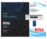


4. WIRING DIAGRAM (BUILT-IN ISO)
6
CONNECTOR
ISO
1
2
1
2
3
4
7
5
6
8
7
5
3
8
6
4
C
O
N
N
E
C
T
O
R
B
Figure 2
C
O
N
N
E
C
T
O
R
A
ISO CONNECTOR WIRING CHART
YELLOW
WIRE COLOR
VIOLET/BLACK
GREY/BLACK
GREEN/BLACK
WHITE/BLACK
VIOLET
WHITE
GREY
B1
B5
B4
B3
B2
B8
GREEN
B7
B6
A5
A4
PIN
BLACK
A8
RED
A7
BLUE
LEFT FRONT SPEAKER (-)
LEFT REAR SPEAKER (+)
LEFT REAR SPEAKER (-)
RIGHT REAR SPEAKER (+)
RIGHT FRONT SPEAKER (+)
LEFT FRONT SPEAKER (+)
RIGHT FRONT SPEAKER (-)
RIGHT REAR SPEAKER (-)
FUNCTION/LABEL
POWER ANTENNA
B)
IGNITION(ACC)
GROUND
R
E
A
R
L
IN
E
O
U
T
R
-C
H
R
E
A
R
L
IN
E
O
U
T
L-
C
H
REAR
L
R
F
U
S
E
iPod
iPod READY CABLE
WHITE
A
M
P
BLACK
FRONT LINE OUT
R
-C
H
L
-C
H
RED
WHITE
RCA-TO-RCA CABLE
(not supplied)
AMP
ANTENNA
JACK
ANTENNA
EXTENDER
CABLE
Summary of Contents for MR1525UI
Page 1: ...4 10 R 02 0896 ...


