background image


60

Editing a recorded performance (Track Edit)


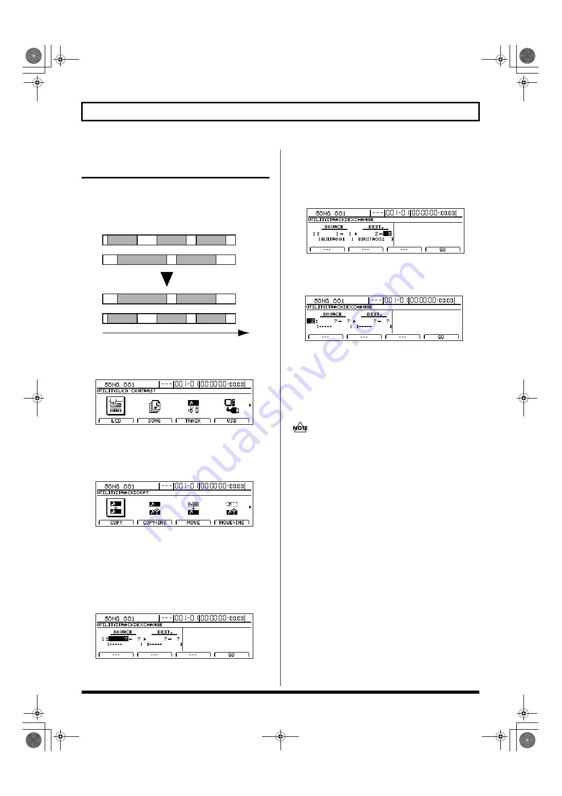
Exchanging audio data 


(Track Exchange)


The Track Exchange function allows you to exchange the all 
recorded data between two different tracks.


Example: Exchanging all data between Tracks 1 and 2


fig.15-33


1.


Press [UTILITY].


The Utility Menu screen will appear.


fig.12-12d


2.


Move the cursor to the TRACK icon and press [ENTER/YES].


Alternatively, you can press [F3] (TRACK) if the TRACK 
icon is currently displayed. 

The Track Menu screen will appear.


fig.15-05d


3.


Move the cursor to the EXCHANGE icon and press 
[ENTER/YES].


Alternatively, you can press [F1] (EXCHANGE) if the 
EXCHANGE icon is currently displayed. 

The Track Exchange screen will appear, allowing you to 
select the tracks and V-Tracks to be used as the exchange 
source and destination. 


fig.15-36d


4.


Use [CURSOR] and the TIME/VALUE dial to choose 
the tracks and V-Tracks between which you want to 
exchange audio data. 


If a name has been assigned to the selected track, it will 
be displayed at this time.


fig.15-37d


5.


If you want to exchange audio data between other 
tracks, move the cursor to the position shown below 
and turn the TIME/VALUE dial.


fig.15-38d


You will now be able to specify other tracks as the source 
and destination of another exchange operation. 

In this case, it is not possible to specify a destination 
track that coincides with another source track.

If you want to cancel the exchange of data between 
specific tracks, turn the TIME/VALUE dial 
counterclockwise until a question mark (?) is displayed.


• Data exchange will not be performed for any line 

containing one or more question marks.

• As Tracks 9/10 through 15/16 are stereo tracks, it will 

not be possible to select either of their mono tracks 
independent of the other.


6.


When you have made all of the necessary track 
selections, press [F4] (GO).


The audio data will now be exchanged, and when the 
message “Complete!” appears, it indicates that this 
operation has been completed. 


7.


Press [EXIT/NO] several times to return to the top 
screen.

Track 1

Track 2

Track 1

Track 2

A

A

B

B

C

C

D

D

E

E

Time

BR-1600_R_e.book 60 ページ 2007年12月6日 木曜日 午前9時52分

Summary of Contents for Digital Recording Studio BR-1600 CD

Page 1: ...Owner s Manual Basic Operation explains the sequence of turning on this unit recording playback mixing down and making an original Audio CD To use the BR 1600CD please read this book first Owner s Ma...

Page 2: ...cept when this manual provides specific instructions directing you to do so Refer all servicing to your retailer the nearest Roland Service Center or an authorized Roland distributor as listed on the...

Page 3: ...tion or position does not interfere with their proper ventilation 102c Always grasp only the plug on the AC adaptor cord when plugging into or unplugging from an outlet or this unit 103b At regular in...

Page 4: ...mage or malfunction may result if you attempt to use the unit in this condition Therefore before using the unit you must allow it to stand for several hours until the condensation has completely evapo...

Page 5: ...ird party We assume no responsi bility whatsoever with regard to any infringements of third party copyrights arising through your use of this unit About the License Agreement The BR 1600CD and its CD...

Page 6: ...t table edges when it is being moved Positioning the BR 1600CD close to drums during performances Positioning the BR 1600CD close to amplifiers for guitars and other musical instruments during perform...

Page 7: ...o become accustomed to the new environment allow a few hours before operating it Avoid using the CD R RW drive in locations with high temperatures Failure to observe this precaution can result in the...

Page 8: ...le to remove a CD R RW disc Inserting a CD R RW disc 1 Press the eject button and open a disc tray 2 Pull out a disc tray 3 Locate the position of center hole of CD R RW disc at stopper of CD R RW dri...

Page 9: ...ons and add the audio to your tracks without using this CD ROM However in case you initialize your hard disk drive in the BR 1600CD or accidentally erase the User Loop Phrases you can recover all of t...

Page 10: ...jack 35 INPUT 1 MIC 1 jack 35 INPUT 2 MIC 2 jack 35 INPUT 3 MIC 3 jack through INPUT 8 MIC 8 jack 35 DIGITAL IN connector 35 Output jacks and connectors 36 LINE OUT jacks 36 DIGITAL OUT connector 36 P...

Page 11: ...rker 48 Basic marker operations 48 Positioning a marker 48 Clearing markers 48 Moving to markers 48 Editing markers 49 Moving markers 49 Naming a marker 49 Assigning an audio CD song division to a mar...

Page 12: ...a song Song Protect 71 Removing song protection 71 Naming a song Song Name 72 Saving your song Song Save 72 Section 2 Using Effects 73 Makeup of BR 1600CD effects 74 Using insert effects 76 Effect pa...

Page 13: ...er functions 90 Acoustic Guitar Simulator 90 Acoustic Processor 90 3 Band Equalizer 91 4 Band Equalizer 91 Bass Simulator 92 Bass Cut Filter 92 Chorus 92 2x2 Chorus 92 Compressor 93 COSM Comp Limiter...

Page 14: ...1 Using loop effects 112 About loop effects 112 About loop effect connections 112 Basic loop effect operations 113 Adjusting the sound of loop effects 113 Adjusting reverb 113 Adjusting chorus 114 Adj...

Page 15: ...Low Freq Trimmer 128 High Freq Trimmer 128 Limiter 128 Using the Mastering Tool Kit 129 The Mastering Tool Kit 129 Makeup of the Mastering Tool Kit 129 Modifying Mastering Tool Kit settings Edit 130...

Page 16: ...Correcting drum patterns Microscope 157 Changing the drum pattern s groove Swing 159 Changing a drum pattern s name 160 Copying drum patterns 160 Deleting drum patterns 161 Loading drum patterns from...

Page 17: ...rhythm arrangements 187 Selecting a rhythm arrangement 187 Changing the rhythm arrangement tempo 187 Setting the tempo using TAP 188 Creating rhythm arrangements 189 Assembling drum and bass patterns...

Page 18: ...Copying waveform data from a computer to the audio tracks WAV AIFF Import 210 Copying audio track waveform data to computers WAV AIFF Export 211 Playing SMFs using external MIDI instruments SMF Player...

Page 19: ...ng of the Insert Effects Effects Program Change 235 Controlling external video devices from the BR 1600CD V LINK 236 What is V LINK 236 What can V LINK do 236 Connecting V LINK devices 236 Using V LIN...

Page 20: ...olume balance 258 Manually adjusting the input volume balance 259 Muting individual inputs 260 Inputting audio with no loss of quality Digital In Assign 261 Creating a master tape protected from digit...

Page 21: ...AR BASS is selected 281 When VOCAL is selected 282 When SIMUL is selected 282 When MULTI TRACK is selected 283 When STEREO TRACKS is selected 284 REC MODE Recording Mode Operations 285 Internal connec...

Page 22: ...en later on this feature allows you to do so with ease A host of digital effects The BR 1600CD provides you with a full range of powerful effects for many different situations In specific terms Insert...

Page 23: ...easily set the tempo to the right speed What s more you can also combine different drum and bass patterns to create a rhythm section performance with interesting variations at appropriate points duri...

Page 24: ...ord The indicater of the selected button will light If a lit INPUT SELECT button is pressed it will turn off and the corresponding input source s will be muted GUITAR BASS This button is used to selec...

Page 25: ...dio from several tracks and to record it on one or two different tracks MASTERING Allows you to master your finished songs using the BR 1600CD s Mastering Tool Kit If you wish to read more about the v...

Page 26: ...out position To do this hold down DELETE and then press either IN or OUT to delete the corresponding auto punch position When the IN or OUT setting is cleared in this way its indicator will be turned...

Page 27: ...components such as loop phrases bass and drums In this manual the term track faders is used to refer to the AUDIO TRACK MIXER faders 25 Track buttons 1 8 9 10 15 16 Track buttons 1 through 8 and 9 10...

Page 28: ...nd set parameters for Drum Bass Loop Phrase and rhythm arrangements p 145 When ARRANGEMENT PATTERN is lit up Press EDIT to call up a screen for creating rhythm arrangements and editing the relevant pa...

Page 29: ...it is also used to modify values of the various function settings 42 CURSOR buttons Press these buttons to move the cursor in the corresponding direction 43 ENTER YES button Press this button to conf...

Page 30: ...button to eject a CD R RW disc from the drive unit Note that it will only be possible to eject the CD R RW disc while the BR 1600CD is powered up If you need to eject the disc after the power has been...

Page 31: ...in terms of the number of frames At the time of purchase the number of frames per second will initially be set to 30 non drop This represents one type of MIDI Time Code MTC specification and if you wa...

Page 32: ...r of external MIDI devices such as rhythm machines sequencers and sound modules to this connector using a MIDI cable MIDI connectors p 36 Section 5 Using MIDI p 221 6 USB connector Plug a USB cable in...

Page 33: ...nector In addition phantom power at 48 V can be supplied via the XLR connectors Using condenser microphones Phantom Power p 264 If a connection is made to both the 1 4 phone mono jack and the XLR conn...

Page 34: ...on has been made to both of these input jacks the GUITAR BASS jack will be selected automatically 2 PHONES 1 jack Use this jack to connect separately sold headphones 3 PHONES 1 VOLUME knob Adjusts the...

Page 35: ...is used to input unbalanced signals the XLR type connector to input balanced signals In addition the XLR connector can also supply phantom power You can use this input whenever INPUT SELECT VOCAL MUL...

Page 36: ...to the speakers via this connector It is important to note that standard audio cables cannot be used with the DIGITAL OUT connector and that a commercially available digital audio cable or video cabl...

Page 37: ...ill not be able to use the USB connector to access external hard disks CD R RW drives or other similar types of USB device Furthermore this USB connector cannot be used with an audio interface or the...

Page 38: ...ures and beats to the left of this time value The displayed time is based on MIDI Time Code MTC and as such it is presented in terms of hours minutes seconds frames and sub frames Note that different...

Page 39: ...ress or from CURSOR to move the display area up or down respectively When the display area is moved up the black area in the scroll bar will also move up and when the display area is moved down the bl...

Page 40: ...ed counterclockwise VALUE 1 PAN VALUE 2 VALUE 3 and VALUE 4 knobs fig 06 07 These knobs can be used to change the values of parameters indicated by knob icons on screen Turn clockwise to increase a va...

Page 41: ...41 Section 1 Advanced Use Section 1 Advanced Use BR 1600_R_e book 41...

Page 42: ...y foot Performing manual punch in and punch out using REC The following section will describe using manual punch in and punch out to re record a portion of Track 1 which was recorded earlier 1 Press t...

Page 43: ...unch out must be activated at exactly the right time and where you need to concentrate on your performance not the pressing of buttons Specifying the section to be re recorded In order to activate pun...

Page 44: ...it will need to be pressed to turn it off 4 Start playback of your song and use the INPUT LEVEL knob to adjust the volume of the input to an appropriate level 5 When the volume levels have been match...

Page 45: ...rming loop recording As an example the following section will describe usage of the repeat function together with auto punch in and punch out to re record a portion of Track 1 which was recorded earli...

Page 46: ...on the middle left of the display Currently selected V Track containing recorded audio data Currently selected V Track not containing recorded audio data V Track containing recorded audio data V Track...

Page 47: ...the V Track to be written to an audio CD the Final Mastering Track When in Mastering mode the symbol will be automatically placed on the right of the V Track from Track 9 10 that was most recently us...

Page 48: ...mation refer to Naming a marker p 49 Basic marker operations Positioning a marker Press MARK to place a marker at the current song position fig 12 02 Note that markers must be at least 0 1 seconds apa...

Page 49: ...fig 12 08d 2 Move the cursor to Name and then use CURSOR and the TIME VALUE dial to change the marker name fig 12 09d Assigning an audio CD song division to a marker When writing stereo tracks to an a...

Page 50: ...ing or playback at marker positions If the operation i e recording or playback is then restarted it will continue to the next marker where it will again be stopped automatically 1 Press UTILITY The Ut...

Page 51: ...ne it will be overwritten using the current settings To delete Press F2 DELETE The asterisk indicating a registered scene will disappear to show that the scene is no longer registered 5 Press EXIT NO...

Page 52: ...p 75 Mastering Tool Kit p 75 Chorus delay sends for Tracks 1 through 15 16 Reverb sends for Tracks 1 through 15 16 Settings can be made to indicate whether or not EQ and effect parameters will be rest...

Page 53: ...YSTEM icon and press ENTER YES Alternatively you can press F1 SYSTEM if the SYSTEM icon is currently displayed The System Parameter screen will appear 3 Move the cursor to Effects or Track Equalizer a...

Page 54: ...nd the end of a section of audio p 55 Using Scrub to find the start of a section of audio 1 Hold down STOP and press PLAY PLAY will start flashing and scrubbing will begin The level meter for the curr...

Page 55: ...can press F4 SCRUB PRV if the SCRUB PREVIEW icon is currently displayed The Scrub Preview screen will appear 3 Move the cursor to Preview Switch and select ON using the TIME VALUE dial fig 14 04d The...

Page 56: ...t to reuse a recorded phrase from a certain track or when you want to repeat the same phrase again and again When copying audio data you will normally want the start of the copied section to be aligne...

Page 57: ...cks independent of the other 6 Move the cursor to the right half of the screen and specify the copy range and copy destination positions fig 15 21d Pressing F1 DISP FMT at this time will allow you to...

Page 58: ...you could determine the correct destination With this function however you can specify the start point of the explosion in the original data using FROM and the destination where you want the explosio...

Page 59: ...estination positions fig 15 32d Pressing F1 DISP FMT at this time will allow you to select how positions will be specified i e by measure time or marker The following parameters should now be set STAR...

Page 60: ...ed to the selected track it will be displayed at this time fig 15 37d 5 If you want to exchange audio data between other tracks move the cursor to the position shown below and turn the TIME VALUE dial...

Page 61: ...u want to insert a blank space into other tracks using the same settings for position length etc move the cursor to the position shown below and turn the TIME VALUE dial fig 15 44d You will now be abl...

Page 62: ...fig 15 05d 3 Move the cursor to the CUT icon and press ENTER YES Alternatively you can press F4 CUT if the CUT icon is currently displayed fig 15 49d The Track Cut screen will appear allowing you to...

Page 63: ...t to the end of the song press F3 SELECT ALL 7 When you have made all of the necessary settings press F4 GO The audio data will now be deleted and when the message Complete appears it indicates that t...

Page 64: ...is selected Alternatively if you want to select all V Tracks from all tracks select As Tracks 9 10 through 15 16 are stereo tracks it will not be possible to select either of their mono tracks indepen...

Page 65: ...ursor to the right half of the screen and specify the start point and end point for the segment you want to normalize using CURSOR and the TIME VALUE dial The Normalize Time Setting screen will appear...

Page 66: ...segment to be normalized No sound will play back if the segment is shorter than 0 5 seconds The sound is interrupted for an instant about twenty milliseconds immediately before and after the normalize...

Page 67: ...12 12d 2 Move the cursor to the SONG icon and press ENTER YES Alternatively you can press F2 SONG if the SONG icon is currently displayed The Song Menu screen will appear fig 16 03d 3 Move the cursor...

Page 68: ...lowest unused song number will be assigned to the song newly created in the copy process When copying has finished the message Complete will appear and the display will automatically return to the top...

Page 69: ...K will appear fig 16 13d 5 Press ENTER YES The selected song will be erased If you erase the song that is currently loaded the BR 1600CD will select and load the song with the lowest song number If no...

Page 70: ...splayed The message Optimize Song will appear fig 16 16d 4 Press ENTER YES The song optimization process will now begin and when the message Complete appears it indicates that this has been completed...

Page 71: ...ently displayed The Song Menu screen will appear fig 16 03d 3 Move the cursor to the PROTECT icon and press ENTER YES Alternatively you can press F2 PROTECT if the PROTECT icon is currently displayed...

Page 72: ...gs are saved Audio data Mixer settings The Insert Effects song patch i e S001 through S050 S001 through S100 in the case of the Guitar Bank S001 through S010 in the case of the Multi Channel Bank The...

Page 73: ...73 Section 2 Using Effects Section 2 Using Effects BR 1600_R_e book 73...

Page 74: ...qualizers compressors and low cut filters STEREO effects As the name suggests these effects are applied to stereo inputs The STEREO bank features stereo compressors Lo Fi processor ring modulators and...

Page 75: ...rcially available CDs are originally created data is written to them in such a way that the loudest point in each song is close to the maximum volume that can be recorded on the CD A good balance amon...

Page 76: ...ank P001 through P050 Multi channel bank P001 through P010 Stereo bank P001 through P050 Preset patches contain data that has been set up in advance and it will not be possible to write new settings t...

Page 77: ...to get the sound just right When you are saving a preset patch with modified settings you should save it as a user patch or a song patch 1 Press EFFECTS The Effects Patch screen will appear fig 31 01...

Page 78: ...effects using the VALUE knobs The following four knob icons are displayed on the insert effects patch screen fig 31 60 The text above each icon indicates the parameter that has been assigned to it an...

Page 79: ...3 Move the cursor to the effect block whose connection sequence is to be modified and then press F2 MOVE The effect block s icon will change and will appear at the current connection position fig 31...

Page 80: ...PUT 1 and INPUT 2 move the cursor to an effect block displayed on a row with either 1 or 2 on the left hand side Similarly to turn on Stereo Link for INPUT 7 and INPUT 8 move the cursor to an effect b...

Page 81: ...field and select a destination patch using the TIME VALUE dial fig 31 07d FROM This field should be left unchanged at TMP CURRENT If a different message is displayed however move the cursor to this f...

Page 82: ...y return to the Effects Patch screen If you selected a different destination bank than that set by pressing the INPUT SELECT button this new bank selection will be maintained after copying has been co...

Page 83: ...rformed the underlined connections will be automatically selected When connecting to the Track output When connecting to the Master channel output Although the Master channel output is always availabl...

Page 84: ...able Roland EV 5 or BOSS FV 500L FV 500H Connection of any other product can cause the BR 1600CD to malfunction Both the Roland EV 5 and BOSS FV 500L FV 500H have a minimum volume setting of 0 Dependi...

Page 85: ...y change the way in which this algorithm s internal effect blocks are connected fig 31 12 COSM Overdrive Distortion COSM PreAmp Speaker Equalizer Wah 4Band Equalizer Wah Noise Suppressor Foot Volume F...

Page 86: ...microphone fig 31 16 Acoustic Processor Compressor 4Band Equalizer Noise Suppressor Delay 6 BASS MULTI This is a multi effect designed for bass and it is suitable for creating standard bass sounds fig...

Page 87: ...ts fig 31 20 Compressor De esser Enhancer 4Band Equalizer Noise Suppressor Foot Volume Modulation Flanger Chorus Phaser Pitch Shifter Doubling Tremolo Pan Delay 10 VOICE TRANSFORMER This is a multi ef...

Page 88: ...Equalizer Wah Noise Suppressor Foot Volume Modulation Flanger Chorus Phaser Pitch Shifter Doubling Tremolo Pan Delay 14 LO FI BOX This allows you to simulate the sound of audio being played on an AM...

Page 89: ...r use when simultaneously recording a vocal part and acoustic guitar You can create a warm sound for the guitar and make it sound as if a mic were being used even when an electric acoustic is connecte...

Page 90: ...Simulates the sound you would get from a pickup installed on an electric acoustic guitar With this setting a certain amount of compression will be applied during the attack Top Hi 100 100 This adjusts...

Page 91: ...ameter sets the frequency for the low range equalizer Low Q 0 3 16 0 This parameter sets the range of change in gain for the frequency set by Low Freq A larger value results in a narrower range of cha...

Page 92: ...fect that adds different chorus sounds to L and R Pre Delay 0 0 ms 40 0 ms Adjusts the time needed for the effect sound to be output after the direct sound has been output By setting a longer pre dela...

Page 93: ...parameter affects the way in which compression is applied i e the knee in the vicinity of the threshold SOFT With this knee setting compression is applied gently and is gradually increased as the lev...

Page 94: ...effect Attack Time 0 100 Active when VtgRack is selected This parameter adjusts the amount of time it takes for the compression ratio set by Ratio to be reached once the input level exceeds the set t...

Page 95: ...o MIDDLE It is normal therefore to use this setting Speaker SW OFF ON Turns the speaker simulator on or off JC 120 The sound of the Roland JC 120 JAZZCMB The sound suited to jazz FULLRNG This is a sou...

Page 96: ...ts the sensitivity with respect to the input volume and it controls the way in which the effect is applied Level 0 100 Adjusts the overall volume of the effect Defretter This effect simulates the soun...

Page 97: ...s selected Delay Time SINGLE 1 1400 ms PAN 1 700 ms This parameter adjusts the delay time i e the interval over which sound is delayed Distance Microphones often exhibit a boost in the volume of the l...

Page 98: ...the depth of the flanging effect Manual 0 100 This parameter adjusts the center frequency at which the effect will be applied Resonance 0 100 Determines the amount of resonance or feedback Increasing...

Page 99: ...turns the lo fi box effect on or off Effect Type Select the operating mode for the lo fi box RADIO The audio will sound as if it is being played on an AM radio By adjusting Tuning you can simulate th...

Page 100: ...t affect its natural character Effect On Off OFF ON This parameter turns the noise suppressor effect on or off Threshold 0 100 Adjust this parameter to match the volume of the noise If the noise is re...

Page 101: ...ange of a sound will be in steps Step Rate 0 100 This sets the cycle of the step function that changes the rate and depth When it is set to a higher value the change will be finer Effect Level 0 100 T...

Page 102: ...sing this parameter when the expression pedal is depressed Fine 50 50 Make fine adjustments to the pitch shift The amount of the change in the Fine 100 is equivalent to that of the Pitch 1 Pre Delay 0...

Page 103: ...crisper tone This will not be displayed for certain Amp Type settings Gain LOW MIDDLE HIGH Adjusts the distortion generated by the amp with the level increasing in sequence for LOW MIDDLE and HIGH Th...

Page 104: ...ns the speaker simulator effect on or off Speaker Type Selects the type of speaker that will be simulated On Mic simulates the sound obtained using a dynamic microphone Off Mic simulates the sound obt...

Page 105: ...Tremolo is an effect that creates a cyclic change in volume This effect can be used when COSM OD GUITAR AMP algorithm is selected Wave Shape 0 100 This adjusts changes in volume level Rate 0 100 Adjus...

Page 106: ...g the frequency response characteristics of a filter Auto wah modifies the filter in a cyclic fashion or in response to the volume of the input source in order to create automatic wah effects Touch wa...

Page 107: ...COSM OD GUITAR AMP is selected Wah Type Selects either touch wah TOUCH or pedal wah PEDAL TOUCH The effect will function as a touch wah PEDAL The effect will function as a pedal wah When TOUCH is sele...

Page 108: ...s A maximum of 8 different compressors can be used and these can be selected for use on Tracks 1 through 8 or Tracks 9 10 through 15 16 Three band equalizers A three band equalizer separates the track...

Page 109: ...reached once the input level exceeds the set threshold level and compression begins The smaller the value set here the more rapidly compression will be applied RELEASE 0 100 This adjusts the time it t...

Page 110: ...tracks from a stereo pair 3 Press F4 LINK ON Stereo Link will be toggled between on and off 4 If you wish to store the modified settings save the current song p 72 Adjusting a three band equalizer For...

Page 111: ...f you wish to store the modified settings save the current song p 72 Switching equalizers between stereo and mono Stereo Link If you intend to apply an equalizer to a stereo recorded track you will ne...

Page 112: ...repeating the original sound after it is played this effect can add a sense of spaciousness and depth to the sound In addition when this effect is applied to instruments that play melodies it can make...

Page 113: ...of a small room HALL Simulates the reverberation of a concert hall PLATE Simulates the reverberation of reverb devices using large metal plates that have been constant favorites in professional studio...

Page 114: ...modified settings save the current song p 72 Adjusting delay Use the following procedure Delay Edit to make fine adjustments to the delay sound 1 Press CHORUS DELAY The Chorus Delay Send screen will a...

Page 115: ...ft right position of each track Pan Basic Operation p 46 2 Press CHORUS DELAY The Chorus Delay Send screen will appear fig 34 103d 3 Move the cursor to the track to be doubled and select a send level...

Page 116: ...akeup of the Vocal Tool Box The following two types of effects make up the BR 1600CD s Vocal Tool Box Pitch Correction This effect automatically fixes incorrect pitches in solo vocal tracks Specifical...

Page 117: ...cal part contains an excessive number of different pitches such as fast deep vibrato or fast speech When the part is sung with a very low voice containing a lot of harmonics If the BR 1600CD is freque...

Page 118: ...recording 14 If you wish to store the corrected track save the current song p 72 Setting the correction method for vocal pitch Pitch Correction Edit Each of the preset patches 1 through 5 uses a sligh...

Page 119: ...h 15 16 8 Start playback on the BR 1600CD Listen to the backing chorus that will now be applied to the solo vocal part during playback If necessary adjust the volume using the corresponding track fade...

Page 120: ...on a parameter setting screen to jump to the parameter setting screen for the next effect block to the left or right respectively fig 35 10d 4 Move the cursor to the setting you want to change and se...

Page 121: ...s have been temporarily changed the bank number will be displayed as TMP If you select a different patch load a different song or turn off the BR 1600CD while TMP is being displayed all of the patch s...

Page 122: ...UE dial fig 35 14ad FROM This field selects the patch to be copied Although TMP CURRENT may be displayed in this field when you call up the Patch Write Copy screen after modifying patch settings this...

Page 123: ...FILTER block is used to filter out any unwanted low band signals resulting from for example pop noise produced by the vocalist in an otherwise fine performance The LOW FREQUENCY TRIMMER and HIGH FREQ...

Page 124: ...make up the Speaker Modeling feature can be fine tuned by making the appropriate settings Before starting however you will need to select the Speaker Modeling patch that you would like to change 1 Pre...

Page 125: ...gs Patch Write Modified Speaker Modeling settings are saved by writing them together under a new patch name 1 Press F1 NAME on the Speaker Modeling edit screen fig 37 09d 2 Move the cursor to the char...

Page 126: ...at you can also move the cursor to the bank field and turn the TIME VALUE dial to select a new patch number to be copied 3 Move the cursor to the TO field and select a destination patch using the TIME...

Page 127: ...DS 30A speakers are connected Phase Specifies the phase of the speakers NORMAL The output phase will be the same as that of the input INVERSE The output phase will be the opposite to that of the input...

Page 128: ...er frequency for the low frequency trimmer High Freq Trimmer This trimmer is used to process high frequencies On Off OFF ON Switches the high frequency trimmer on or off Gain 12 12 dB Adjusts the gain...

Page 129: ...the frequencies in a musical performance can separated into the following three bands or regions The low band which contains the sounds of the kick drum bass guitar and other instruments that provide...

Page 130: ...ore detailed information regarding settings refer to Mastering Tool Kit parameter functions p 134 3 Move the cursor to the parameter that you want to change and select a new value using the TIME VALUE...

Page 131: ...rsor will be automatically positioned here 6 Press F4 GO The Mastering Tool Kit patch will be written When the message Complete appears it indicates that writing has been completed 7 Press EXIT NO sev...

Page 132: ...e the cursor to AUTO FADE IN and select ON with the TIME VALUE dial 3 Press F3 AUTO FADE The Auto Fade In setting screen will appear fig 36 09d 4 Move the cursor to the setting you want to change and...

Page 133: ...out Adjust the START and LENGTH settings to ensure that the volume smoothly reduces to zero before the end of the song When the current position is after the point corresponding to START LENGTH you wi...

Page 134: ...equalizer type to shelving or peak Low Gain 12 12 dB Sets the amount of boost or cut in the lower band Low Freq 20 Hz 2 0 kHz Sets the center frequency for the lower band Low Q 0 3 16 0 Sets the steep...

Page 135: ...e volume level at which the low band expander begins to affect the sound ExpL Ratio 1 1 00 1 16 0 1 INF Sets the ratio for output increase in the low band when the input level falls below the Lo thres...

Page 136: ...and compressor to start affecting the sound once the input level exceeds the Hi threshold CmpH Release 50 5000 ms Sets the time it takes for the high band compressor to stop affecting the sound once t...

Page 137: ...ESH Release NS REL Foot Volume On Off FOOT ON OFF FX On Off MOD ON OFF FX Select MOD SELECT Compressor Sustain COMP SUST Attack COMP ATTACK Tone COMP TONE Level COMP LEVEL Limiter Threshold LIMITER TH...

Page 138: ...EQ H MID F Hi Mid Q EQ H MID Q High Gain EQ HIGH Level EQ LEVEL Effect Block Parameter Abbreviation Noise Suppressor On Off NS ON OFF Threshold NS THRESH Release NS REL Foot Volume On Off FOOT ON OFF...

Page 139: ...TYPE Feedback DELAY FEEDBCK Effect Level DELAY LEVEL Delay Time DELAY TIME Effect Block Parameter Abbreviation Effect Block Parameter Abbreviation Acoustic Processor On Off AC ON OFF Body AC BODY Mic...

Page 140: ...Wah Wah Type WAH TYPE Polarity T WAH POLARTY Sensitivity T WAH SENS Frequency T WAH FREQ Peak WAH PEAK Level WAH LEVEL Effect Block Parameter Abbreviation Noise Suppressor On Off NS ON OFF Threshold...

Page 141: ...SEP Chorus Rate CHORUS RATE Depth CHORUS DEPTH Pre Delay CHORUS PREDLY Effect Level CHORUS LEVEL Phaser Rate PHASER RATE Depth PHASER DEPTH Manual PHASER MANUAL Resonance PHASER RESO Effect Block Para...

Page 142: ...Attack LIMITER ATTACK Release LIMITER REL Detect HPF LIMITER D HPF Threshold LIMITER THRESH Level LIMITER LEVEL Effect Block Parameter Abbreviation Compressor On Off COMP ON OFF Sustain COMP SUST Atta...

Page 143: ...LUME Bass E AMP BASS Middle E AMP MIDDLE Treble E AMP TREBLE Presence E AMP PRESNC Presence E AMP PRESNC Master E AMP MASTER Bright E AMP BRIGHT Gain E AMP GAIN Speaker Simulator On Off E SP SIM ON OF...

Page 144: ...ter Abbreviation Low Cut Filter n n 1 8 On Off L CUTn ON OFF Invert L CUTn INVERT Freq L CUTn FREQ Compressor n n 1 8 On Off COMPn ON OFF Threshold COMPn THRESH Knee COMPn KNEE Ratio COMPn RATIO Attac...

Page 145: ...145 Section 3 Using Rhythm Section 3 Using Rhythm BR 1600_R_e book 145...

Page 146: ...patches and song drum patches can be overwritten For details on how drums are actually used refer to Using drums p 149 Drums can only be used when Track 15 16 has been set up as a drum track using it...

Page 147: ...for use in any song and 50 song Loop Phrases that are saved together with a specific song User Loop Phrases and song Loop Phrases can be overwritten At the time of purchase the BR 1600CD will contain...

Page 148: ...be overwritten In addition it can also store 10 user rhythm arrangements that can be used in any song and 10 song rhythm arrangements that are saved together with a specific song User rhythm arrangeme...

Page 149: ...t up for use as a drum track 3 Press EXIT NO to return to the top screen You will now be able to use drums 4 If you wish to store the track type setting save the current song p 72 Playing drum sounds...

Page 150: ...off 2 Press PROGRAMMABLE RHYTHM EDIT The Pattern Selection screen will appear fig 20 005d 3 Move the cursor to the drum pattern field and select a pattern using the TIME VALUE dial Playback of the ne...

Page 151: ...tion to setting the tempo using CURSOR and the TIME VALUE dial you can also set it by tapping your finger on TAP at the desired tempo Tap Tempo This feature proves extremely useful when you want to ma...

Page 152: ...NT PATTERN to turn it off 2 Press PROGRAMMABLE RHYTHM EDIT The Pattern Selection screen will appear fig 20 005d 3 Press F4 EDIT The Drum Pattern Edit screen will appear fig 20 010d 4 Move the cursor t...

Page 153: ...unds The relationship between track buttons and drum sounds is as follows 6 If you want to erase an error in the recorded pattern press F3 ERASE ON fig 20 012ad The message ERASE ON will appear and dr...

Page 154: ...ton is recorded as is and any imperfections in timing will be reflected in the performance data If you don t want to hear these imperfections during playback you can use the BR 1600CD s quantize featu...

Page 155: ...the position where a drum sound is to be input and then use the TIME VALUE dial to insert a at that position fig 020 016bd The drum will be played at a high volume The drum will be played at a moderat...

Page 156: ...set here is used only for checking that the drum pattern is as required In other words this tempo will not be saved with the drum pattern It is not possible to set a specific tempo for a drum pattern...

Page 157: ...value using the TIME VALUE dial Larger velocity values produce higher volumes and vice versa To change a drum s gate time 1 Move the cursor to GATE field fig 20 026dd 2 Set a new value using the TIME...

Page 158: ...TE COPY DEL The Write Copy Delete screen for drum patterns will appear fig 20 024d 6 Use the TIME VALUE dial to select the drum pattern to which the data is to be saved Only user drum patterns and son...

Page 159: ...ect for your song Playback of the drum pattern will start Press STOP to end playback 5 If you want to store the swing setting you have just made press F4 WRITE COPY DEL The Write Copy Delete screen fo...

Page 160: ...PY The Write Copy Delete screen for drum patterns will appear fig 20 224d 3 Move the cursor to the FROM field and select the drum pattern to be copied using the TIME VALUE dial fig 20 032cd 4 Move the...

Page 161: ...drum patterns Precautions for SMF import CR R RW discs of ISO9660 Level 2 Mode 1 format are supported for import It will not be possible to import data from discs of any other format SMFs of up to 240...

Page 162: ...g the TIME VALUE dial Only data associated with the specified MIDI channel will be extracted from the selected SMF and imported as a drum pattern fig 20 043ad In the case of SMFs supporting the GM GS...

Page 163: ...Press EXIT NO to return to the top screen You will now be able to use bass 4 If you wish to store the track type setting save the current song p 72 Playing bass Simply changing the track type may not...

Page 164: ...T The Pattern Selection screen will appear fig 20 005d 3 Move the cursor to the bass pattern field and select a pattern using the TIME VALUE dial or the VALUE 3 knob Playback of the newly selected bas...

Page 165: ...ATTERN to turn it off 2 Press PROGRAMMABLE RHYTHM EDIT The Pattern Selection screen will appear fig 20 005d 3 Press F1 SETUP The dialog for pattern setup will appear fig 20 006d 4 Move the cursor to C...

Page 166: ...s button s indicator is lit which means you re in Arrangement mode press PROGRAMMABLE RHYTHM ARRANGEMENT PATTERN to turn it off 2 Press PROGRAMMABLE RHYTHM EDIT The Pattern Selection screen will appea...

Page 167: ...recorded at the same time position as a previously recorded note priority will be given to the newer note and only this will be retained in other words the previously recorded note will be deleted Not...

Page 168: ...ce data will be recorded Recording in perfect time Quantize With real time recording the data generated by pressing a track button is recorded as is and any imperfections in timing will be reflected i...

Page 169: ...he data is moved down by one octave In total the data can be raised or lowered by a maximum of two octaves 6 Press the track button for the note to be entered Performance data will be input each time...

Page 170: ...any of the corresponding parameters can be corrected as required 1 Press F3 MICROSCOPE on the Bass Pattern Edit screen The Microscope screen will appear fig 20 068d Performance data is displayed on t...

Page 171: ...ition 3 Press EXIT NO to end Microscope editing The Bass Pattern Edit screen will appear once again fig 20 151d 4 If you want to store the bass pattern that you have just corrected press F4 WRITE COPY...

Page 172: ...rrect for your song Playback of the drum pattern will start Press STOP to end playback 5 If you want to store the swing setting you have just made press F4 WRITE COPY DEL The Write Copy Delete screen...

Page 173: ...COPY The Write Copy Delete screen for bass patterns will appear fig 20 254d 3 Move the cursor to the FROM field and select the bass pattern to be copied using the TIME VALUE dial 4 Move the cursor to...

Page 174: ...s patterns Precautions for SMF import CR R RW discs of ISO9660 Level 2 Mode 1 format are supported for import It will not be possible to import data from discs of any other format SMFs of up to 240 KB...

Page 175: ...nnel will be extracted from the selected SMF and imported as a bass pattern In the case of SMFs supporting the GM GS or XG standards bass type performance data is generally assigned to MIDI channel 2...

Page 176: ...e track will be used for recorded audio LOOP PHRASE The track will be used to play a Loop Phrase You should select LOOP PHRASE here The LOOP PHRASE indicator from TRACK TYPE SELECT will light up to in...

Page 177: ...hrase selection save the current song p 72 The song Loop Phrases contained in the BR 1600CD at the time of purchase are empty you won t hear anything if you select one of them It is important to remem...

Page 178: ...po differs considerably from the original tempo 4 After you have set the tempo press EXIT NO several times to return to the top screen 5 If you wish to store the pattern s tempo save the current song...

Page 179: ...Loop Phrase 1 Press CD R RW LOOP PHRASE IMPORT The Loop Phrase screen will appear fig 20 090d 2 Move the cursor to BY TRACK icon and press ENTER YES The Loop Phrase Create By Track screen will be dis...

Page 180: ...unction you will be able to import audio data from commercially available sampling CDs and from CD R or CD RW discs that you have created using a PC Only data of the following format can be imported W...

Page 181: ...peration is in process press EXIT NO When the message Cancel appears press ENTER YES to confirm cancellation A certain amount of time may pass between pressing of EXIT NO and display of the confirmati...

Page 182: ...ny of the loop phrases in the bank Example 1 The bank only contains loop phrases with a BPM setting of 100 100 x 0 75 75 100 x 1 5 150 The allowed settings fall in the range from 75 and above and 150...

Page 183: ...splayed values represent the number of samples from the beginning of the Loop Phrase On the BR 1600CD 44 100 samples correspond to one second of playback The start and end positions of the Loop Phrase...

Page 184: ...button allocation save the current song p 72 Copying Loop Phrases 1 Press CD R RW LOOP PHRASE IMPORT The Loop Phrase screen will appear fig 20 090d 2 Move the cursor to the COPY icon and press ENTER...

Page 185: ...2 Move the cursor to the ERASE icon and press ENTER YES The Loop Phrase Erase screen will appear fig 20 110d 3 Select the Loop Phrase to be deleted using the TIME VALUE dial If you press F2 PREVIEW a...

Page 186: ...TERN to turn it off 2 Press PROGRAMMABLE RHYTHM EDIT The Pattern Selection screen will appear fig 20 005d 3 Press F1 SETUP The dialog for pattern setup will appear fig 20 006d 4 Move the cursor to Bea...

Page 187: ...only be dark or flashing 5 Raise the faders for Tracks 11 12 through 15 16 to suitable levels These tracks will now be set up for playback of a rhythm arrangement 6 Press PLAY to start playback The dr...

Page 188: ...rrangement s tempo save the current rhythm arrangement p 195 The tempo set for Pattern mode p 151 p 165 p 178 and the tempo set for Arrangement mode are handled separately Setting the tempo using TAP...

Page 189: ...mbled patterns as required press EXIT NO to return to the Rhythm Arrangement Selection screen 8 To save your pattern allocations carry out the procedure described below in Modifying all of the loop ph...

Page 190: ...ME VALUE dial while a track button is being held to select different types of chords Selectable chord types N C non chord Select this type of chord if you want the original Bass Pattern to be played w...

Page 191: ...this action Inserting chords Use the following procedure to insert a new chord between two existing chords 1 On the chord input screen move the cursor to the chord immediately in front of the insertio...

Page 192: ...with the beginning of the measure BOTTOM The Loop Phrase is aligned with the end of the measure 7 Move the cursor to LEN and set the length of the selected Loop Phrase as a number of measures Note th...

Page 193: ...ing procedure in the screen for assembling Loop Phrases into rhythm arrangements to insert a new Loop Phrase between two that have already been positioned 1 Move the cursor to MEASURE and select the m...

Page 194: ...you want to set the range as extending from the start of the song to the end of the Loop Phrase s press F3 SELECT ALL 5 Once you ve made all the necessary settings press F4 GO The message Now Copying...

Page 195: ...loop phrases with varying tempos with BPM settings of 100 120 and 140 The fastest of these tempos is the BPM setting of 140 140 x 0 75 105 The slowest of these tempos is the BPM setting of 100 100 x...

Page 196: ...l to select the rhythm arrangement to which the data is to be saved Only user rhythm arrangements and song rhythm arrangements may be selected for saving rhythm arrangement data You will not be able t...

Page 197: ...4 Press F4 GO A confirmation message will appear fig 21 32d 5 If you are sure you want to delete the rhythm arrangement press ENTER YES Press EXIT NO to cancel deletion The rhythm arrangement will be...

Page 198: ...for the change in tempo and it can be set within a range of 1 to 999 The position of the first tempo map entry is fixed at 1 and cannot therefore be changed You can create up to 50 tempo maps If the s...

Page 199: ...ter sets the measure position for the change in beat and it can be set within a range of 1 to 999 The position of the first time signature map entry is fixed at 1 and cannot therefore be changed You c...

Page 200: ...3 Press EXIT NO to return to the top screen fig 21 42d The metronome icon will be displayed on the top right of the screen You will now be able to use the metronome 4 If you wish to store the track ty...

Page 201: ...or both of the PHONES 1 or PHONES 2 jacks At the time of purchase the BR 1600CD will be set up to output metronome playback to both of the headphone jacks 1 Press UTILITY The Utility screen will appea...

Page 202: ...will be output via this output ON The metronome will be output via PHONES 2 At the same time the audio form input playback sound on the Tracks drum bass patterns and Loop Phrases will be mixed output...

Page 203: ...203 Section 4 Using the CD R RW Drive Section 4 Using the CD R RW Drive BR 1600_R_e book 203...

Page 204: ...ion press F1 once again If you would like to back up all songs on the hard disk in a single operation press F2 ALL All songs will be selected for backup To cancel this selection press F2 once again Th...

Page 205: ...S once again The BR 1600CD will begin writing data to the CD R RW disc When the message Complete appears it indicates that the backup has been successfully completed Backing up user data User Backup T...

Page 206: ...e supported speeds using the TIME VALUE dial If you are using CD R RW discs intended for high speed writing the frequency of write errors may increase if the x2 or x4 speed is selected It is recommend...

Page 207: ...covery You will not be able to select any songs or data types that have not been saved to the CD R RW disc If the current song contains newly recorded audio data or newly modified settings the message...

Page 208: ...been completed successfully Reading backup user data back into the hard disk User Recover 1 Insert a CD R RW disc containing backup user data into the BR 1600CD s CD R RW drive The drive s access ind...

Page 209: ...Insert a CD R RW disc containing an HDD backup into the BR 1600CD s CD R RW drive The drive s access indicator will begin to flash Wait until this indicator stops flashing and turns off before proceed...

Page 210: ...older name and icon is displayed To show the WAV files within the folder move the cursor to the folder name and press ENTER YES fig R16 94d 6 To switch the format of the wave file you want to import p...

Page 211: ...re usable Copying audio track waveform data to computers WAV AIFF Export You can write data for specified tracks to a CD R RW disc as waveform data then import the waveform data to the computer using...

Page 212: ...s end point 8 When you have finished making the settings press F4 GO The message Write Speed appears fig R16 93d 9 Rotate the TIME VALUE dial to set the write speed Write Speed x2 352 Kbps Writes twi...

Page 213: ...s indicator will begin to flash Wait until this indicator stops flashing and turns off before proceeding 3 Press CD R RW DATA SAVE LOAD The Data CD screen will appear fig 41 05d 4 Press F3 SMF The fun...

Page 214: ...til this indicator stops flashing and turns off before proceeding 2 Press CD R RW DATA SAVE LOAD The Data CD screen will appear fig 41 05d 3 Move the cursor to the ERASE icon and press ENTER YES The m...

Page 215: ...ss ENTER YES Alternatively you can press F1 SYSTEM if the SYSTEM icon is currently displayed The System Parameter screen will appear fig 10 03d 3 Move the cursor to CD Hold Time and set a suitable tim...

Page 216: ...e CD creation process to allow song lengths to be adjusted without having to record silence at the end of each 1 Press AUDIO CD WRITE PLAY The Audio CD screen will appear fig 40 01d 2 Press F1 WRITE T...

Page 217: ...not want to erase the disc press EXIT NO The data erasure will begin and the state of progress will be displayed When the message Complete appears and the track buttons begin to flash the erasure is c...

Page 218: ...drive s EJECT button to eject the disc What is finalizing In addition to the audio data itself other information describing the position and time of this data is also written to audio CDs This proces...

Page 219: ...YES The message Now Importing will appear and import to the audio track will begin When the message Complete appears it indicates that the import procedure has been successfully completed Important N...

Page 220: ...220 MEMO BR 1600_R_e book 220...

Page 221: ...221 Section 5 Using MIDI Section 5 Using MIDI BR 1600_R_e book 221...

Page 222: ...MIDI OUT port but not with a MIDI THRU port MIDI channels The MIDI standard allows data to be exchanged among multiple MIDI compatible devices using a single MIDI cable and this is made possible by w...

Page 223: ...ss Note Channel and set a suitable MIDI channel using the TIME VALUE dial OFF Note messages will not be transmitted for bass 1 through 16 Note messages for bass will be transmitted on the selected MID...

Page 224: ...nge the sounds assigned to the various note numbers Refer to the user s manual for the MIDI sound module for details on how this is done Drum name Note number Kick 1 C 2 36 Snare 1 D 2 38 Closed hi ha...

Page 225: ...MIDI sequencers and rhythm machines In this case the MIDI timing clock is used as the synchronization master Specifically the MIDI timing clock is a signal that is transmitted six times per sixteenth...

Page 226: ...nc Synchronizing a MIDI sequencer to the playback time using MTC The term MIDI Time Code MTC refers to a type of time synchronization message that is output every frame in order to allow MIDI sequence...

Page 227: ...type accordingly 30 30 frames per second non drop format This format is generally used with audio devices such as analog tape recorders and with NTSC black and white video devices as used in Ja pan a...

Page 228: ...example the following offset times can be set in order to have external MIDI devices play back at the MTC times shown below when the BR 1600CD s song time is 01h00m00s00 3 Press EXIT NO several times...

Page 229: ...cording stop playback on the external MIDI sequencer or rhythm machine The recording of MIDI timing clock signals will stop automatically and the display will return to the top screen This completes t...

Page 230: ...icon and press ENTER YES Alternatively you can press F2 SYNC if the SYNC icon is currently displayed The synchronization setting screen will appear fig 50 06d 3 Move the cursor to Sync Offset and set...

Page 231: ...refer to MIDI Implementation p 288 5 Press EXIT NO move the cursor to the SYNC icon and then press ENTER YES Synchronization using MTC will now be possible For more details see Step 4 and subsequent s...

Page 232: ...mission and reception of fader operations via MIDI on and off At the time of purchase MIDI Fader will be turned off so you will need to turn this function on if you intend to use it 1 Press UTILITY Th...

Page 233: ...different faders any fader operation data received on that channel will be used to operate all of the corresponding faders simultaneously Confirming the current fader positions When fader operation d...

Page 234: ...ce any sound when you press a key on a MIDI keyboard This is due to the fact that only a predetermined range of note numbers have been assigned sounds whether it be with drums or with bass For more de...

Page 235: ...received Simultaneously the insert effects patch bank is switched according to the Bank Select message received immediately before this In addition when an insert effects patch is selected on the BR 1...

Page 236: ...D s MIDI OUT port to the DV 7PR s remote terminal using a UM 1 When using a DV 7PR start up Presentation Mode on that device Using V LINK fig 51 02 1 Press V LINK This button will light up V LINK will...

Page 237: ...an the top screen when V LINK is turned on If you press a track button while holding down V TRACK Palette 1 through Palette 12 will be assigned to the track buttons for Tracks 1 through 8 and Tracks 9...

Page 238: ...With V LINK REC lit up carry out the following procedure 1 Press ZERO to jump to the start of the song and then press PLAY The playback of recorded V LINK control operations will start as the BR 1600...

Page 239: ...239 Section 6 Using USB Section 6 Using USB BR 1600_R_e book 239...

Page 240: ...ponsibility for the incorrect operation of the BR 1600CD or for the loss of data resulting from the failure to observe this precaution Do not perform the following actions when switching to USB mode o...

Page 241: ...fig 52 02 When you double click the BR 1600CD icon or the Removable Disk icon in Windows or double click the BR 1600CD icon in Mac OS all of the files and folders contained in the BR 1600CD s hard di...

Page 242: ...fig 52 07 5 Double click the BR 1600CD or Removable Disk icon The files and folders from the BR 1600CD s hard disk will be displayed on the PC monitor fig 52 08 6 Select all of the files and folders...

Page 243: ...nnect your computer and the BR 1600CD with a USB cable 2 Confirm that the recorder is stopped then press UTILITY The Utility Menu screen will appear fig 12 12d 3 Move the cursor to the USB icon and pr...

Page 244: ...In this case pressing ENTER YES returns the USB menu screen to the display 9 Press EXIT NO to return to the Top screen At this point you can safely disconnect the USB cable from the BR 1600CD and the...

Page 245: ...52 07 6 Open the folder on the PC where you have stored the backup data All of the backup files and folders will appear on screen 7 Select all of the backup files and folders 8 Copy them to the BR 160...

Page 246: ...the computer With Macintosh 1 Initialize the BR 1600CD s hard disk p 270 Note that all of the data on the BR 1600CD s hard disk will be deleted as a result of this operation and if necessary you shou...

Page 247: ...ppear in the display and the most recently selected song will be reloaded When reloading has been completed the display will return to the USB screen If you press EXIT NO without quitting the connecti...

Page 248: ...Select the track combination 1 2 15 16 fig 52 16d 6 Use the TIME VALUE dial to select the file format WAV This is an audio format used primarily with Windows AIFF This audio format is used primarily w...

Page 249: ...will be displayed once again WAV or AIFF files will be automatically deleted from the BR 1600CD s internal hard disk If you are using an OS other than Windows Me the BR 1600CD will automatically retu...

Page 250: ...mat used primarily with Windows AIFF This audio format is used primarily with Macintosh 7 Press F4 GO Conversion of the WAV or AIFF file begins The correspondence between tracks and converted file nam...

Page 251: ...se pressing ENTER YES returns the file format selection screen to the display 13 When you have finished exporting the WAV or AIFF file s press EXIT NO several times to return to the Top screen At this...

Page 252: ...een will appear fig 52 05d 4 Move the cursor to the IMPORT icon and press ENTER YES Alternatively you can press F3 IMPORT The USB Import screen will appear fig 52 22d 5 Use CURSOR and the TIME VALUE d...

Page 253: ...ox that appears 12 Press BR 1600CD s EXIT NO The WAV and or AIFF files will be converted into audio track data When this process has been completed the USB Import screen will be displayed once again T...

Page 254: ...t proper importation of WAV and AIFF files so be sure to delete any such files 10 Drag and drop the WAV or AIFF file to be imported on the computer to the USB folder Only one file can be imported at a...

Page 255: ...255 Section 7 Other Convenient Functions Section 7 Other Convenient Functions BR 1600_R_e book 255...

Page 256: ...quired setting press TUNER ON OFF once again or press EXIT NO The tuner will be turned off 4 If you wish to store the modified settings save the current song p 72 Tuning The following describes the tu...

Page 257: ...ON OFF or press EXIT NO The tuner will be turned off Precautions for tuner usage Neither playback nor recording is possible while the tuner is being used Effects will also be inactive at this time En...

Page 258: ...RACKS mode In this case the audio from the input sources will be mixed in stereo and then recorded on the track selected for recording 3 Press LEVEL CALIBRATION This button will light up and the messa...

Page 259: ...evels 4 Press EXIT NO several times to return to the top screen 1 2 3 4 Adjustment of the balance of input levels is only possible when MULTI TRACK or STEREO TRACKS has been selected from INPUT SELECT...

Page 260: ...g 53 06d 2 Press F3 MANUAL Levels will be displayed for each input fig 53 100d 3 Turn muting for input sources on and off using the FUNCTION buttons F1 through F4 When muting has been turned on for an...

Page 261: ...o mix Alternatively if MULTI TRACK or STEREO TRACKS from INPUT SELECT is currently turned on the left and right audio signals from the DIGITAL IN connector will be routed to INPUT 1 and INPUT 2 respec...

Page 262: ...ix down your song s from the BR 1600CD to a DAT recorder or another similar digital device It will not be possible to use this master tape to create digital copies on another similar digital recording...

Page 263: ...1 Press UTILITY The Utility screen will appear fig 12 12d 2 Move the cursor to the SYSTEM icon and press ENTER YES Alternatively you can press F1 SYSTEM if the SYSTEM icon is currently displayed The...

Page 264: ...ors for INPUT 1 through INPUT 8 Phantom power Condenser microphones generally contain a pair of thin opposing electrodes When a voltage is applied across these electrodes any vibration resulting from...

Page 265: ...for INPUT 1 through INPUT 8 or to the GUITAR BASS jack The phantom power setting reverts to OFF whenever the BR 1600CD is turned on Remember therefore to turn on this power supply whenever it is need...

Page 266: ...e to record this audio to tracks Audio Sub Mix is set up as described below fig 53 21 1 Press UTILITY The Utility screen will appear fig 12 12d 2 Move the cursor to the SYSTEM icon and press ENTER YES...

Page 267: ...User patches from all insert effect banks Vocal Tool Box user patches Mastering Tool Kit user patches Speaker Modeling user patches fig 53 28 1 Press UTILITY The Utility screen will appear fig 12 12d...

Page 268: ...rsor to the icon for the parameters to be initialized and press ENTER YES Alternatively you can push the FUNCTION button below the relevant icon The message Initialize OK will appear Example When GLOB...

Page 269: ...s indicated by an asterisk 4 If you want to switch the partition being used move the cursor to the partition you want to use then press ENTER YES The message Now Loading appears When Complete appears...

Page 270: ...tions each containing 40 GB You cannot create a 80 GB partition SURFACE SCAN The entire hard disk is formatted as NORMAL after all of the storage sectors of the hard disk are checked With a 80 GB hard...

Page 271: ...e cursor to the HDD icon and press ENTER YES The Hard Disk screen will appear fig 54 02d 4 Move the cursor to the INITIALIZE icon and press ENTER YES The Hard disk Initialize screen will appears fig 5...

Page 272: ...272 MEMO BR 1600_R_e book 272...

Page 273: ...273 Appendices Appendices BR 1600_R_e book 273...

Page 274: ...r position Has the track been muted The REC TRACK indicator will be blinking in green Is the V Track setting for a different V Track Has the track type been set correctly Is the BR 1600CD in Mastering...

Page 275: ...e margin of headroom Also since the MIC 1 and MIC 2 jacks are low impedance inputs the recording level may be too low depending on the response of some mics In such cases connect the mic via a mic pre...

Page 276: ...I sequencer ready to play back Does the other device support the MMC commands of the BR 1600CD Cannot record MIDI Clock cannot use the sync track Is the external MIDI sequencer set to transmit MIDI Cl...

Page 277: ...t Cause 1 You attempted to load a waveform file lasting 0 5 seconds or less Action 1 Prepare the waveform file so that it is longer than 0 5 seconds Cause 2 You attempted to write an audio CD with a t...

Page 278: ...orm the Song Optimize operation p 70 Marker Memory Full Cause The BR 1600CD has used up all the marker memory 100 markers that can be handled by one song Action Delete unneeded markers Medium Error Ca...

Page 279: ...Select the data before continuing Stop Recorder Cause The operation you attempted cannot be done while the recorder is running playing or recording Action Press STOP to stop playback or recording Syn...

Page 280: ...nnected to the GUITAR BASS jack the INPUT 1 MIC 1 jack will be deactivated An effect will be automatically selected from the insert effects SIMUL bank and this will be applied both to the GUITAR BASS...

Page 281: ...nsert Effects Recording track mono GUITAR BASS INPUT 1 MIC 1 INPUT SENS 1 Impedance Conversion Input 1 Reverb Send PEAK Input 1 Chorus Delay Doubling Send L R If an instrument is connected to the GUIT...

Page 282: ...UT1 MIC1 If an instrument is connected to the GUITAR BASS jack the INPUT 1 MIC 1 jack will be deactivated INPUT SENS 1 INPUT LEVEL L R PEAK 1 L R INPUT2 MIC2 PEAK 2 INPUT SENS 2 Recording track L R L...

Page 283: ...d Input 4 Chorus Delay Doubling Send L R Recording track 5 or 13 INPUT 5 MIC 5 INPUT SENS 5 Input 5 pan L R Input 5 Reverb send Input 5 Chorus Delay Doubling Send L R Recording track 6 or 14 INPUT 6 M...

Page 284: ...8 MIC 8 INPUT SENS 8 Input 8 Pan PEAK Level Calibration Insert Effects INPUT LEVEL Insert Effects L R When insert effects are connected to INPUT 1 8 When insert effects are connected to INPUT 1 8 LIN...

Page 285: ...ration All track playback rhythm guide performances and other audio that can be heard via the LINE OUT jack or the PHONES 1 jack will be recorded to the selected track As a result moving the MASTER fa...

Page 286: ...R Track 13 Track 14 Level Meter Pre Fader Level Meter Post Fader When insert effects are connected to Track 13 14 Track 15 16 Pan Track15 16 Fader Track15 16 Equalizer Insert Effects L R Track15 16 Ch...

Page 287: ...LINE OUT PHONES L R Mastering Tool Kit Track9 10 Fader Track 9 Track 10 Level Meter Pre Fader Level Meter Post Fader Master Fader AUDIO SUB MIX L R L R V Track on Track 9 10 to be subjected to masteri...

Page 288: ...the MIDI parameter MIDI Fader SW is set to ON controls the effects in the same manner as operating the EXP PEDAL Program Change Status 2nd byte CnH ppH n MIDI channel number 0H FH ch 1 ch 16 pp Progra...

Page 289: ...ce ID then rotate the TIME VALUE dial to set the device ID The Device ID can be set to any number from 17 to 32 It was set to 17 at the factory 2 Data Transmission Channel Voice Messages Note off Stat...

Page 290: ...us 2nd byte 3rd byte BnH 42H vvH n MIDI channel number 0H FH ch 1 ch 16 vv Control value 00H 7FH 0 127 0 63 OFF 64 127 ON SOFT Controller number 67 Status 2nd byte 3rd byte BnH 43H vvH n MIDI channel...

Page 291: ...nel number 0H FH ch 1 ch 16 vv Channel Pressure 00H 7FH 0 127 Transmitted according to the content of the SMF during playback of SMFs Pitch Bend Change Status 2nd byte 3rd byte EnH llH mmH n MIDI chan...

Page 292: ...7EH dev 06H 02H 41H 71H 01H F7H 00H 00H 00H 00H 00H 00H Byte Remarks F0H Exclusive status 7EH ID number Universal Non realtime Message dev Device ID dev 10H 1FH 06H Sub ID 1 General Information 02H S...

Page 293: ...98 62H 3 03H 35 23H 67 43H 99 63H 4 04H 36 24H 68 44H 100 64H 5 05H 37 25H 69 45H 101 65H 6 06H 38 26H 70 46H 102 66H 7 07H 39 27H 71 47H 103 67H 8 08H 40 28H 72 48H 104 68H 9 09H 41 29H 73 49H 105 6...

Page 294: ...1 127 64 1 127 1 0 127 O O 1 1 O 1 O O O O 1 2 2 O X O O O 0 127 1 O O O X X 4 5 O O O O 5 5 5 5 O O O O O O O X 1 1 1 1 1 1 1 16 1 16 Memorized X X X 1 127 X X 0 127 DRUMS 27 75 BASS 0 72 X X X O 0...

Page 295: ...20 kHz 1 3 dB Total Distortion 0 025 or less INPUT SENS CENTER 1 kHz at nominal output level Nominal Input Level Variable GUITAR BASS jack 10 dBu MIC 1 8 jacks XLR 40 dBu INPUT 1 8 jacks 10 dBu Input...

Page 296: ...SB 7U Owner s Manual Basic Operation Owner s Manual Data List Insert Effect Patch List etc Roland Service information sheet CD ROM DISCRETE DRUMS Options Expression Pedal EV 5 Roland Foot Volume Expre...

Page 297: ...GC3K 100 Algorithm 77 85 ALL 181 185 208 ALL icon 268 Amb Density 96 Amb HF Damp 96 Amb Level 96 Amb Pre Dly 96 Amb Size 96 Ambience 96 AMERCAN 94 AMG 103 104 amg 104 Amp Type 103 ARRANGEMENT 209 Arra...

Page 298: ...37 BUTTON ASSIGN 184 BY TRACK 179 C CALCULATE 258 CANCEL 79 CD Hold Time 215 CD hold time 215 CD player 216 CD Track 49 CD R disc 7 CD R RW 29 203 CD R RW disc 7 Compatibility 8 Inserting 8 Precaution...

Page 299: ...DATA SAVE LOAD button 29 DC IN AC adaptor jack 32 37 D Comp 94 De esser 87 96 DEFAULT 113 115 Defretter 85 86 96 DELAY 114 Delay 75 85 89 97 112 Delay Time 97 104 135 Delay time 114 DELAY TYPE 115 DE...

Page 300: ...er Edit screen 110 Equalizer screen 110 Equalizer Wah 85 ERASE 189 193 238 Erase CD RW disc 214 217 Loop phrase 185 ERASE icon 63 69 185 214 217 ERASE OFF 153 167 ERASE ON 153 167 Erasing 63 Error mes...

Page 301: ...er 128 HIGH FREQUENCY 111 HIGH GAIN 111 High Gain 91 105 134 High Level 93 136 High Pre Dly 93 HIGH Q 111 High Q 91 134 High Rate 93 HIGH TYPE 110 High Type 91 134 High speed writing 205 207 Hi Mid Fr...

Page 302: ...on 29 Loop Phrase screen 179 Loop Recording 45 LOW 103 110 LOW CUT 113 114 Low Cut Filter 99 Low Depth 92 Low Freq 91 134 Low Freq Trimmer 128 LOW FREQUENCY 111 LOW GAIN 111 Low Gain 91 105 134 Low Le...

Page 303: ...N 222 MIDI IN connector 32 36 MIDI indicator 29 MIDI keyboard 234 MIDI OUT 222 MIDI OUT connector 32 36 MIDI screen 223 231 MIDI sequencer 225 MIDI sound module 223 MIDI THRU 222 MIDI time code 226 MI...

Page 304: ...Phaser 85 87 88 101 PHONES 1 jack 34 PHONES 1 VOLUME knob 34 PHONES 1 2 jacks 36 PHONES 2 jack 34 PHONES 2 VOLUME knob 34 Phones2 202 PIC 101 Pickup Simulator 85 101 Pickup Type 90 PIEZO 90 Pitch 102...

Page 305: ...71 Repeat 45 REPEAT button 26 RES 155 169 RESET 258 Resonance 96 98 100 101 REST 169 Rest 120 Reverb 74 112 REVERB button 27 113 Reverb Edit 113 Reverb Edit screen 113 REVERB SEND 115 Reverb Send 121...

Page 306: ...eter 127 Speaker Modeling patch 124 Speaker Modeling patch screen 124 Speaker Modeling Patch Write Copy screen 126 Speaker Simulator 86 88 104 Speaker SW 95 Speaker Type 96 104 Split Freq H 135 Split...

Page 307: ...1 FADER 51 SCENE 51 Track Move 58 Track Move screen 58 TRACK MUTE button 28 Track Name 47 Track screen 56 Track status 27 Track type 149 163 176 200 TRACK TYPE indicators 29 TRACK TYPE SELECT 149 163...

Page 308: ...L BOX button 27 117 119 Vocal Tool Box Write Copy screen 121 122 Voice 102 Voice character 106 VOICE TRANSFORMER 87 Voice Transformer 87 106 VOICE1 120 VOL 192 Volume 103 Volume pedal 84 Volume swell...

Page 309: ...309 MEMO BR 1600_R_e book 309...

Page 310: ...For EU Countries BR 1600_R_e book 310...

Page 311: ...cept when this manual provides specific instructions directing you to do so Refer all servicing to your retailer the nearest Roland Service Center or an authorized Roland distributor as listed on the...

Page 312: ...Owner s Manual Basic Operation explains the sequence of turning on this unit recording playback mixing down and making an original Audio CD To use the BR 1600CD please read this book first Owner s Ma...

Reviews: