18
REMOTE
TAS1020B
USB Controller and
Microprocessor
5V 3.3V
WM8772 or AK4626
CODEC
o
D
DACs
ADCs
TI DSP
TMS320DA710
3.3V 1.2V
Audio clock
master
Audio clock
slave
Audio clock
slave
McASPs
EEPROM
I2C Bus
EEPROM
I2C Bus
RAMP
GENERATOR
TOUCH
SENSOR
Bass Knob
Thermistor
MUTE
Volume
Headphone
Aux In
USB Input
3.3V
VRAW
Thermistor
113 115 116
120 119
RT6307
RT6206
Q6101
135
131
134
U7000
27
28
25
23
26
24
9
6
D-
D+
5V
38
26
25
7
6
U6000
U4000
Q6202
Q6203
Audio Path
U1000
Out to
Amplifier
31
138
BADDATA
30
127
DSPINT
122
126
CCLIP
BSCLIP
Audio Path (continued)
CODEC
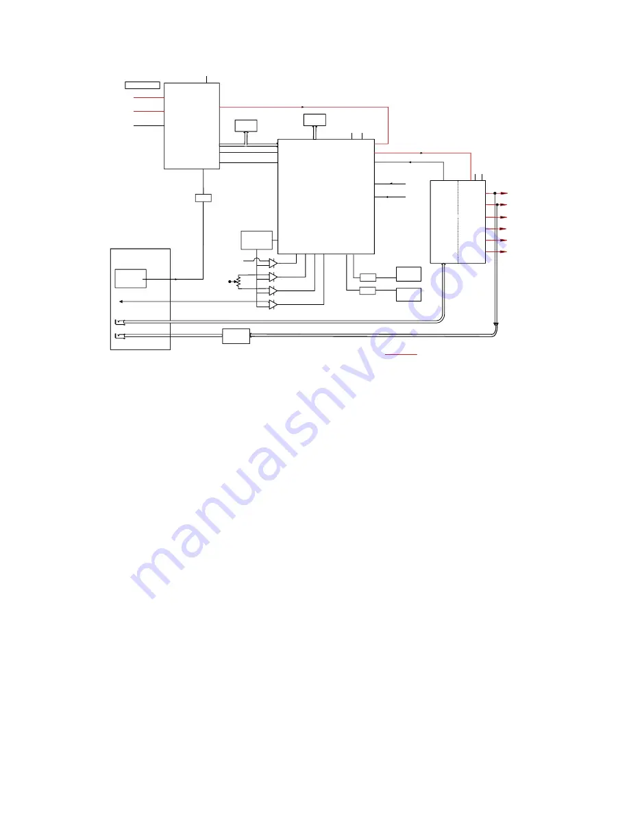
The Codec, U4000, is an AKM4626A. It features the ability to be either hardwired or serial interface configurable.
For this application, it is configured by hardwiring the pins.
Stand-by Operation
DSPRESET\ is used to power down some of the internal functions of the CODEC in order to conserve power
during stand-by operation. The CODEC is active at all other times
CODEC Audio Inputs and Outputs
The DSP receives warning of a USB audio data checksum error on the BADDATA input, U7000.138. All other
connections to the USB controller and DSP are to implement the TDM audio path.
Six channels of audio output are provided by the CODEC. These six outputs are filtered to remove out-of-band
noise and attenuated 7.5dB to reduce the overall gain of the system and AC coupled to the six power amplifiers
in IC’s U150, U250, and U350. The outputs are single-ended biased to approximately 2.5 volts. The maximum
amplitude for a full-scale digital input signal is approximately 1 volt rms. Of the six channels output by the
CODEC, only five are wired to the Amplifiers. The DAC_BASS1 channel (U4000.23) is used to drive both bass
amplifiers.
DAC_LC (U4000.27) and DAC_RC (U4000.28) are also used to drive the headphone amplifiers
(U1000).
Aux Audio Input
The AUX stereo input from the control module is attenuated by -4.3dB. This prevents a
2.0Vrms sine wave input signal from clipping the ADC input, whose max input is 1.0 to 1.1 volts
rms. The converted stereo signal is transmitted to the DSP over the TDM path described in the
next section.


