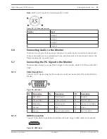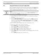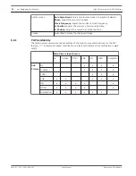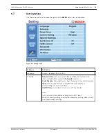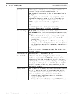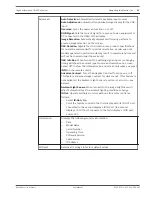
Note: Both Y and C inputs are terminated with 75 Ohm.
Figure 5.3: Y/C Connector pin-out
Number
Input
1
Ground
2
Ground
3
Y-signal
4
C-signal
Connecting Audio to the Monitor
There are two (2) sets of stereo audio connectors for audio inputs, located on the rear panel.
These audio inputs are not associated with any input terminals on the rear panel, and can be
freely connected to any audio input.
Connecting the PC Signal to the Monitor
There are several ways to connect the PC signal to the monitor: HDMI, DVI, VGA and DISPLAY
PORT.
VGA Connection
Connect the PC signal using the VGA connector on the rear panel and a VGA cable (D-SUB to
D-SUB).
Figure 5.4: VGA Input
Pin
Description
Pin
Description
Pin
Description
1
Red Video
6
Red Ground
11
Ground
2
Green Video
7
Green Ground
12
SDA (for DDC)
3
Blue Video
8
Blue Ground
13
H-Sync or H+V Sync
4
Ground
9
N/A
14
V-Sync
5
Ground
10
Signal Cable Detect
15
SCL (for DDC)
HDMI Connection
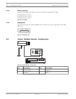
Connect to the HDMI (High Definition Multimedia Input) using a HDMI cable (not supplied).
Figure 5.5: HDMI Input
5.6
5.7
5.7.1
5.7.2
High Performance HD LED Monitor
Installing the Monitor | en
19
Bosch Security Systems
User Manual
2013.07 | v1.0 | F.01U.286.147
Summary of Contents for UML-463-90
Page 1: ...High Performance HD LED Monitor UML 463 90 en User Manual ...
Page 2: ......
Page 41: ......


