1 695 104 941
2008-10-17
|
Robert Bosch GmbH
20 | TCE 4510 | Adjustments
en
Adjustments
3.
Adjustment or replacement of the
3.1
transmission belts
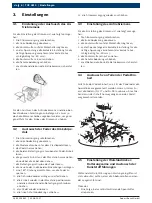
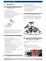
To adjust the belt:
Disconnect power supply;
1.
Remove the left closure cover;
2.
Open the counter-nut on the motor support;
3.
Operate on the tie rod to achieve the correct tension
4.
(the correct excursion is about 50mm);
Tighten again the counter-nut.
5.
Close the protection cover;
6.
Test correct functioning.
7.
To replace the belt follow in any case the instruction
described above; the only precaution is that the re-
ducer pulley has to be disconnected in order to have
enough space for the insertion of the belt.
Replacement of the inverter spring
3.2
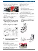
Disconnect power supply;
1.
Remove the left closure cover;
2.
Unscrew the grub screw under the plastic pedal;
3.
Take off the pedal;
4.
Unscrew the two screws that hold the inverter as-
5.
sembly in position;
Extract out of the machine the entire assembly with-
6.
out disconnecting the wires;
Remove the screw that holds the spring in position;
7.
Insert the new spring in the two cuts;
8.
Make a 180° rotation to charge the spring;
9.
Insert the spring and tighten it;
10.
Put again the inverter assembly in its position and
11.
screw it inside the tyre changer;
Mount the pedal;
12.
Close the left cover;
13.
Connect power supply.
14.
Adjustment of the transmission belts
3.3
To adjust the belt:
Disconnect power supply;
1.
Remove the left closure cover;
2.
Open the counter-nut on the motor support;
3.
Operate on the tie rod to achieve the correct tension
4.
(the correct excursion is about 50mm);
Tighten again the counter-nut.
5.
Close the protection cover;
6.
Test correct functioning.
7.
Replacement of pedal box parts
3.4
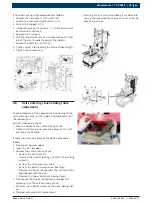
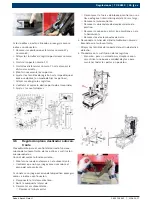
If it is necessary to replace some items of the pedal
box, like the pedal or the ratchet, remember to always
disconnect the springs first (n°77 and n°93), you can
then proceed extracting the axle and replacing the
pedal.
86
85
84
83
87
82
88
81
80 79
78
77
76
75
74
70
71
72
73
106
107
108
109
105
104
97
96
93
98
99
101
100
110
103
102
89
90
91
92
94
95
Adjustment of the bead-breaker arms
3.5
and replacement of the sliders
During technical assistance always check that the roll-
ers are aligned.
Procedure:
Mount a rim on the self-centering chuck;
1.
Bring the upper roller in contact with the rim;
2.
Check that the lower roller is at the same distance
3.
(max 1mm).

