


Rexroth IndraDrive
Determination of Appropriate Power Supply Units
8-1
DOK-INDRV*-HMV-*******-PR01-EN-P
8
Determination of Appropriate Power Supply Units
8.1 Introduction
The mains supply for an AC drive system of the IndraDrive M product
family mainly consists of the power supply unit. Depending on the tasks
and design of the supply unit and the conditions of its use, it may be
necessary to add link reactors, auxiliary capacitors, bleeder modules and
transformers as needed.
The mains supply must make available to the drives the DC bus
continuous power and the DC bus peak power for acceleration. During
regenerative operation it must be able to store continuous and peak
regenerated power. The supply unit also makes the control voltage for the
drive controllers available.
Prior to selecting supply unit and auxiliary components it is necessary to
determine the motors and drive controllers which will be used.
It is advisable to carry out calculations in accordance with the following
chapters in order to make sure that the layout of the mains supply is
correct.
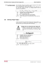
8.2
DC Bus Continuous Power
The DC bus continuous power is calculated from the mechanical power
and based on the efficiency of motor and controller as well as coincidence
factors.
9550
n
*
M
]
kW
[
P
or
60
n
2
*
M
M
]
W
[
P
m
m
=
π
=
ω
∗
=
P
m
:
mechanical power
M:
torque [Nm]
ω
:
angular speed [min
-1
]
n:
motor speed [min
-1
]
Fig. 8-1:
Mechanical power
The effective motor torque and average motor speed are needed to
calculate the mechanical continuous power of a servo drive.
The effective motor torque of the servo drive calculations can be
assumed. The average motor speed is determined as follows:
The average motor speed equals approximately 25% of the rapid motion
speed - in the case of servo drive tasks in conventional NC machine tools.
In some cases, however, this approximate estimation is not sufficient. A
precise calculation of the average motor speed is necessary.
Mechanical power
Continuous mechanical power
for servo drives
Average motor speed
Summary of Contents for Rexroth IndraDrive HMV01.1E-W0030
Page 30: ...5 2 Transport and Storage Rexroth IndraDrive DOK INDRV HMV PR01 EN P Notes ...
Page 40: ...6 10 Mechanical Mounting Rexroth IndraDrive DOK INDRV HMV PR01 EN P Notes ...
Page 88: ...9 8 Control Mains Contactor Rexroth IndraDrive DOK INDRV HMV PR01 EN P Notes ...
Page 122: ...13 22 Appendix Rexroth IndraDrive DOK INDRV HMV PR01 EN P Fig 13 25 HFD01 2 480 0026 ...
Page 123: ...Rexroth IndraDrive Appendix 13 23 DOK INDRV HMV PR01 EN P Fig 13 26 HFD02 2 480 0026 ...
Page 130: ...14 6 Index Rexroth IndraDrive DOK INDRV HMV PR01 EN P Notes ...
Page 131: ......