background image

Bosch Rexroth AG

Bgm.-Dr.-Nebel-Str. 2

97816 Lohr a.Main

Germany

Tel. +49 9352 18 0

Fax +49 9352 18 8400

www.boschrexroth.com/electrics

R911418823

© Bosch Rexroth AG 2022

DC-AE/EPI5 (AnBe/MaKo/MePe)

2

1

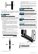
Fig. 12: Positioning connector

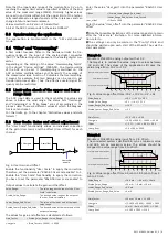
9.6 Notes on the electrical connection

For the front connector, one-wire cables and stranded

cables can be used with or without wire end ferrule (acc.

to DIN 46228). These wire end ferrules can be with or

without plastic collar. The contact surface has to be 8 mm.

The wire ends may not have any burrs.

The cable cross-section allowed is between 0.25 mm

2

 and

1.5 mm

2

 (AWG 24 to 16).

The stripping length is 8 mm.

To use stranded cables without wire end ferrules, twist

the strand between 180° and 360°. The stripped area

has to be 8 mm after twisting. If stranded cables are

introduced, keep the pushbutton of the push-in terminal

pressed.

To remove the cables, press the pushbutton of the push-in

terminal.

To guarantee an UL/CSA-compliant operation, the fol-

lowing conditions have to be met:

Use only insulated copper wires suitable for at least 60

°C

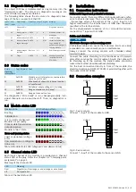
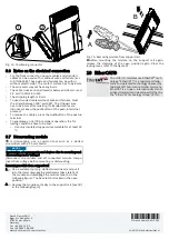
9.7 Dismounting module

For  dismounting,  use  a  common  tool  such  as  a  slotted

screwdriver with a 2.5 mm blade.

NOTICE

Destruction of components and devices due to mounting and

dismounting under voltage!
Disconnect  the  module  and  all  connected  module  compo-

nents from voltage before mounting or dismounting.

Removing module from support rail
1.

Use a suitable tool (e.g. slotted screwdriver) and put it

into the lower disengaging mechanism (base latch) of

the module and disengage the module (see (A) in the

following figure). The base latch is locked in the open

position.

2.

Remove the module vertically to the support rail [see (B)

in the following figure].

A

B

Fig. 13: Removing module from support rail

Before  mounting  the  module  on  the  support  rail  again,

release  the  clamping  of  the  open  position  again.  Press  the

locking lever, refer to the figure 11.

10 EtherCAT

®

The ctrlX I/O modules use EtherCAT

®

 tech-

nology. "EtherCAT®" is a registered trade-

mark and patented technology licensed by

the Beckhoff Automation GmbH, Germany.

EtherCAT is an open, internationally stand-

ardized standard and developed further by

the "EtherCAT Technology Group" (ETG).

Summary of Contents for Rexroth ctrlX I/O XI312204

Page 1: ...cal data 3 1 General technical data XI312204 Number of inputs 4 Connection method Push in XI312204 Connection method 2 wire shielded twisted in pairs Signal type Differential Input signal 0 V to 10 V Input resistance 250 kΩ Limit frequency of input filter 12 8 kHz Conversion time 100 μs Resolution D A 16 bits incl sign Accuracy Typ 0 1 of the end value of the measured range MBE Max 0 3 of MBE Over...

Page 2: ...mi sinusoidal 15 g Broadband noise Acc to DIN EN 60068 2 64 20 500 Hz with 1 22 g RMS 30 min in all three axes For the current approvals go to www boschrexroth com electrics 4 For your safety 4 1 Intended use Only use the module as specified in the data sheet 4 2 User qualification The product use described in this data sheet is only intended for qualified electricians and staff trained by these q...

Page 3: ... the gain and the offset Value_Range The value range at the input of the User Scale calculation Scaled_Value_Range The desired value range at the output of the User Scale calculation Lower_Range_End_Value The value at the lower end of the input value range Scaled_Lower_Range_End_Value The desired value at the lower end of the output value range The values for gain and offset are calculated as foll...

Page 4: ... 6010 6020 6030 Channel 1 2 3 4 60x0 01 Value Int16 IN mV 60x0 02 Underrange Bit IN W 0x2360 60x0 03 Overrange Bit IN W 0x8910 60x0 04 Limit 1 2Bit IN Bit0 Value Limit 1 Bit1 Value Limit 1 60x0 06 Limit 2 2Bit IN Bit0 Value Limit 2 Bit1 Value Limit 2 Index hex Object name Data type Direc tion Error warning informa tion Diagnostic number description Unit A000 0 Material number String 20 IN A010 0 F...

Page 5: ...input value and the diagnostic data in the Compact representation Word 1 INT IN Channel 1 Value Word 2 INT IN Channel 2 Value Word 3 INT IN Channel 3 Value Word 4 INT IN Channel 4 Value Word 5 Byte 1 Byte 2 Bit 0 Bit 1 Bit 2 Bit 3 Bit 4 5 Bit 6 7 Bit 2 Bit 3 Bit 4 5 Bit 6 7 IN IN IN IN IN IN IN IN IN IN IN IN Periphery voltage ok Error Channel 1 Wire break Channel 1 Overrange Channel 1 Limit 1 Cha...

Page 6: ...or peripheral voltage error RD RD RD RD RD RD RD RD RD RD Communication or configura tion error RD RD RD RD RD Table 3 Module status LED diagnostic and device status 8 5 Channel status LED Each input channel of the module is provided via a channel status LED at the plug Refer to Chapter 3 2 Clamping point assignment on page 1 Meaning of the channel LED LED Meaning Red Signal error Overrange or und...

Page 7: ...vide the following minimum distances for sufficient cooling 35 mm 0 mm 0 mm 35 mm 35 mm Fig 10 Ventilation distance Additionally provide sufficient distance for mounting dis mounting plugs and cables If more devices are connected in series to the station on the left or right the surface temperature may not exceed 60 C In case of a several line design the supply air has to be measured under each li...

Page 8: ... to be met Use only insulated copper wires suitable for at least 60 C 9 7 Dismounting module For dismounting use a common tool such as a slotted screwdriver with a 2 5 mm blade NOTICE Destruction of components and devices due to mounting and dismounting under voltage Disconnect the module and all connected module compo nents from voltage before mounting or dismounting Removing module from support ...

Reviews: