R911418823, Edition 01, 7 / 8
U
P
24 V
GND
+
Input
Input
+
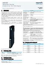
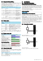
Fig. 9: 4-wire sensor
It is recommended to use the same supply for the voltage
supply of the sensor as for U
P
of the module. The connection
via the potential distribution terminals XI821116, XI822116 or
XI824116 is the recommended connection.
9.3 Installation notes
NOTICE
Device destruction due to electrostatic discharge
The device contains components that can be damaged
or destroyed by electrostatic discharge. Comply with the
required safety measures against electrostatic discharge
(ESD) acc. to EN 61340-5-1 when operating the module.
–
Mounting location
The module has the degree of protection IP 20 and is
thus intended for use in a closed control cabinet or con-
trol box (terminal box) with the degree of protection IP
54 or higher. The control cabinet has to be provided
with sufficient stability and rigidity (acc. to UL 61010-1,
61010-2-201).
–
End clamps
Fasten end clamps of the type SUP-M01-ENDHALTER
(R911170685) on both sides of the station. End clamps
ensure the correct fastening on the support rail and are
used as lateral end elements. Always fasten one end clamp
of the station before mounting the station. This ensures
the following:
•
It impedes the shifting of the modules
•
The installation place for the end clamps is secured.
–
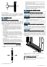
Support rail
Mount the module on a 35 mm standard support rail.
Use only a TH 35-7.5 support rail acc. to EN 60715. The
fastening distance of the support rails may not exceed
200 mm. This distance is required to ensure stability while
mounting and dismounting the module.
< 200 mm
_
–
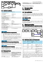
Provide the following minimum distances for sufficient
cooling:
35 mm
0 mm
0 mm
35 mm
35 mm
Fig. 10: Ventilation distance
–
Additionally, provide sufficient distance for mounting, dis-
mounting, plugs and cables.
–
If more devices are connected in series to the station on
the left or right, the surface temperature may not exceed
60° C
–
In case of a several line design, the supply air has to be
measured under each line and its limit value may not be
exceeded. For the permitted ambient temperatures, refer
to the chapter "Ambient conditions".
9.4 Mounting the ctrlX I/O module
NOTICE
Damage of the device by plug mounting under voltage!
Disconnect the module and all connected module compo-
nents from voltage before mounting or dismounting.
NOTICE
Possible damage to property due to unintended mounting of
the support rail
−
Connect the support rail to a functional ground.
−
Mount the module on a support rail.
−
Install the module in a control cabinet or an appropriate
housing.
NOTICE
Module is not fixed correctly due to engaged support arm
mounting!
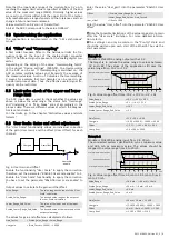
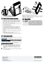
Before mounting, ensure that the support arm mounting of
the control is not in open position. If required, release the
clamping of the open position using the locking lever, refer to
the following figure 11.
NOTICE
Damage of the device by short circuit of patch connectors
There is an endcover on the right of the bus coupler upon
delivery. Remove this endcover to connect the modules in
series at the bus coupler. Position the endcover on the last
module of the station to protect it against short circuit and
contamination.
Fig. 11: Locking lever to release the clamping of the open
position
Each module has to be snapped separately.
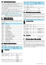
9.5 Positioning connector
1.
Position the connector on the connector holder, see
①
.
2.
Engage the connector, see
②
.

