Bosch Rexroth ctrlX HMI DE0015 Operating Instructions Manual Download Page 36

10.4  Dismounting

1. Disconnect the operator display from voltage.
2. Remove all connected cables.
3. Loosen the screws at the support arm fixture.
4. Remove the display from the support arm fixture.

10.5  Electric installation

10.5.1  Connecting the display to the 24 V voltage supply

1. Connect the "X1S1" interface for the 24 V voltage supply to the industrial

power supply unit.
For the voltage supply, use a 24 V industrial power supply unit acc. to DIN

EN  60742,  classification  VDE  551,  for  example  "VAP01.1H-W23-024-010-

NN" (part number R911171065).

UPS

The display immediately darkens in case of a power failure if the op-

erator display is directly connected to the 24 V supply voltage with-

out UPS. The user cannot execute any actions via the operator dis-

play during the shutdown of the control cabinet PC.
If the operator display is connected together with the control cabi-

net  PC  to  the  "24  V  Out"  of  the  external  UPS  (VAU  02.1),  the  user

can still access the operator display during shutdown due to a pow-

er failure.

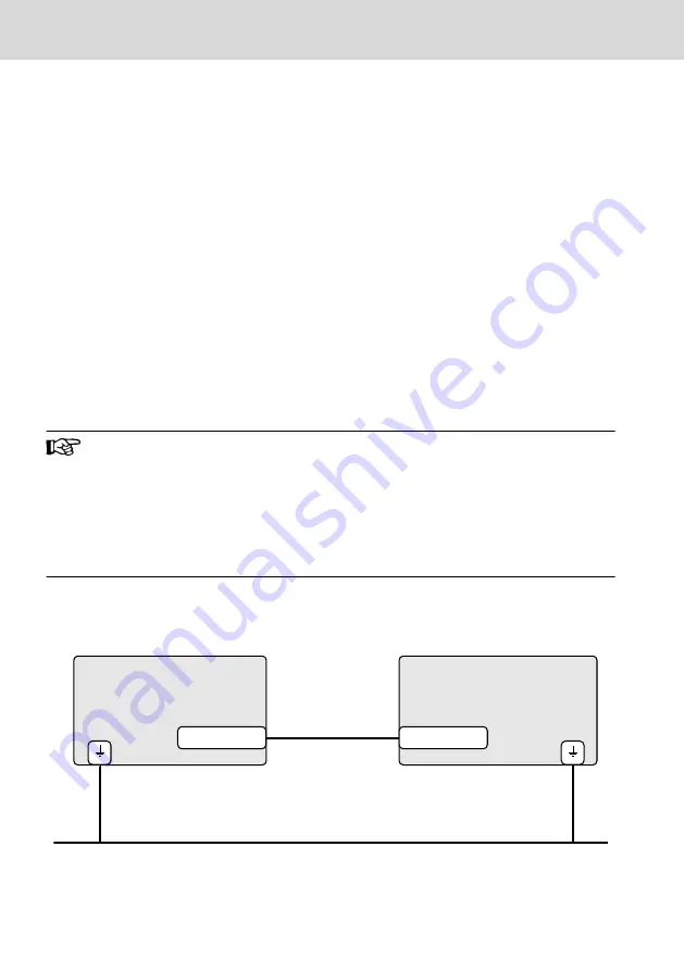
10.5.2  Connecting the control cabinet PC to operator display

Exemplary connection diagram of a CDI+ display connection.

Control cabinet PC

Operator display

XCDI+tx

Functional earth

XCDI+rx

Fig.  10-16:   Wiring the control cabinet PC to the operating display

30/45
Mounting and electrical installation

 ctrlX HMI DE0015, DE0021 Multi-Touch

Displays (Housing Devices)

Bosch Rexroth AG R911405731_Edition 02

Summary of Contents for Rexroth ctrlX HMI DE0015

Page 1: ...ctrlX HMI DE0015 DE0021 Multi Touch Displays Housing Devices Operating Instructions R911405731 Edition 02 ...

Page 2: ...the event of applications for industrial property rights Liability The specified data is intended for product description purposes only and shall not be deemed to be a guaranteed characteristic unless expressly stipulated in the contract All rights are reserved with respect to the content of this documen tation and the availability of the product Editorial Department Development Automation Systems...

Page 3: ...ymbol on the device 5 4 Intended use 5 4 1 Intended use of E STOP control units 6 5 Spare parts accessories and wear parts 7 5 1 External 24 V power supply unit 7 5 2 Uninterruptible power supply 7 5 3 Connecting cables for CDI interface 7 5 4 USB connecting cables USB 2 0 8 5 5 Connecting cables of the display port 8 5 6 Support arm adapter 8 5 6 1 Housing coupling 9 5 7 Wear parts 9 6 Ambient co...

Page 4: ...9 10 2 1 Fastening to the support arm adapter VESA with VAS09 1 001 19 10 2 2 Fastening to an adapter for the tube mounting with VAS09 1 002 25 10 3 Installation notes 29 10 4 Dismounting 30 10 5 Electric installation 30 10 5 1 Connecting the display to the 24 V voltage supply 30 10 5 2 Connecting the control cabinet PC to operator display 30 11 Commissioning 31 11 1 Prerequisites for the initial ...

Page 5: ...4 1 Display 38 14 2 Cleaning notes 38 14 3 Scheduled maintenance tasks 38 15 Ordering information 38 15 1 Accessories and spare parts 38 15 2 Type code for DE devices 39 15 3 Type code for VAS devices 40 16 Disposal 40 16 1 Return 40 16 2 Packaging 40 17 Service and support 41 Index 43 ctrlX HMI DE0015 DE0021 Multi Touch Displays Housing Devices III Table of Contents R911405731_Edition 02 Bosch Re...

Page 6: ...IV ctrlX HMI DE0015 DE0021 Multi Touch Displays Housing Devices Bosch Rexroth AG R911405731_Edition 02 ...

Page 7: ...ps Activities Design engineer Programmer Technologist Process specialist Select Prepare Design Construct Mechanic electrician Unpack Mount Install Programmer Commissioning engineer Parameterize Program Configure Simulate Technologist Process specialist Optimize Test Machine operator Maintenance technician Service Operate Maintain Remove faults Create the NC program Mechanic electrician Disposal co...

Page 8: ...re Applications R911384733 Project Planning Manual VAU 02 1 Uninterruptible Power Supply R911384726 Operating Instructions Rexroth IndraControl PR31 and VR31 Control Cabinet PC and Panel PC R911397432 Project Planning Manual Rexroth IndraControl PR4 and VR4 Control Cabinet PC and Panel PC R911384697 Project Planning Manual IndraControl PR and VR Devices Accessories R911384727 Project Planning Manu...

Page 9: ... Voltage specification In 24 V DC Current specification In 1 5 A Ambient temperature T amb 0 55 C Certification markings UL FCC China RoHS Tab 2 1 Specifications on the type plate example 2 2 Scope of delivery Multi touch display Safety instructions 24 V connection terminal E Stop terminal Key terminal 3 Using safety instructions 3 1 Structure of the safety instructions The safety instructions are...

Page 10: ...006 The signal word draws attention to the safety instruction and indicates the risk potential The safety alert symbol triangular safety reflector with exclamation marks preceding the signal words Danger Warning Caution indicates hazards for persons DANGER In case of non compliance with this safety instruction death or serious injury will occur WARNING In case of non compliance with this safety in...

Page 11: ...h a Bosch Rexroth control cabinet PC Risk of damaging the device if not expressly sta ted accessories mounting parts and other com ponents cables lines software and firmware are used NOTICE The operator displays may only be used as intended and with the accessories mounting parts and other components specified in this documentation Compo nents that are not expressly mentioned must neither be attac...

Page 12: ...es to protect per sons E STOP control units are used for a fast switch off to reach a safe state for machines vehicles and systems and to avoid or reduce hazards and damages to people and machines The following regulations apply in particular to commissioning use and technical inspections Machinery directive 2006 42 EC Safety regulations Accident prevention regulations safety rules Manufacturers a...

Page 13: ...e only cables listed in the following overview Ordering code Part number Description RKB0008 000 5 R911171484 Length 0 5 m RKB0008 001 0 R911171485 Length 1 m RKB0008 002 5 R911170151 Length 2 5 m RKB0008 005 0 R911170152 Length 5 m RKB0008 007 5 R911172971 Length 7 5 m RKB0008 010 0 R911170153 Length 10 m RKB0008 015 0 R911171183 Length 15 m RKB0008 020 0 R911171184 Length 20 m RKB0008 025 0 R911...

Page 14: ...rovided with a special shielding The display port cables meet the following specifications Conform to the display port 1 2 Resolutions up to 4096 2160 Supports HDCP 1 3 and DPCP Ordering code Part number Description RKB0063 003 0 R911391713 Connecting cable of the display port length 3 m RKB0063 005 0 R911391714 Connecting cable of the display port length 5 m 5 6 Support arm adapter Ordering code ...

Page 15: ...aped mounting surface 46 mm 46 mm Tab 5 4 Housing couplings for VAS09 1 002 NNN NN 5 7 Wear parts Wear parts are not subject to any warranty Backlight The service life of the backlight is limited After this period the backlight will produce only 50 of its original brightness The service life is 50 000 hours if the ambient temperature is 25 C 6 Ambient conditions Humidity 85 at 40 C non condensing ...

Page 16: ...DE0015 DE0021 Display 396 mm TFT 15 1366 768 pixels 16 7 million colors 546 mm TFT 21 1920 1080 pixels 16 7 million colors Weight 6 8 kg without support arm adapter 8 2 kg with VAS09 1 002 8 5 kg with VAS09 1 001 9 6 kg without support arm adapter 11 kg with VAS09 1 002 11 3 kg with VAS09 1 001 Power consump tion 20 6 W max 32 W max Input voltage 24 V DC 25 20 24 V DC 25 20 Operation Projected cap...

Page 17: ... the manufacturer and is defined by the respective incoming inspection of the vendor 7 2 2 Input system or multi touch front The maximum permissible number type and size of defects on the front on the glass or between the display and the front such as trapped dust dirt and scratches is defined in the FT quality guideline 8 Standards The products have been developed according to the German editions...

Page 18: ...ial environments and comply with the following requirements Standard Title DIN EN 61000 6 2 Electromagnetic compatibility EMC Part 6 2 Generic standards Noise immunity for industrial environments IEC 61000 6 2 2019 DIN EN 61000 6 4 Electromagnetic compatibility EMC Part 6 4 Generic standards Emission standard for industrial environments IEC 61000 6 4 2007 A1 2011 Tab 8 2 Standards for electromagne...

Page 19: ...ted or miss ing certification Thus verify the registration according to the UL marking on the device Loss of UL CSA conformity due to modifications at the device UL and CSA marking applies only to the device upon delivery After modifying the device verify the UL and the CSA conformity 9 Interfaces Fig 9 1 Interfaces 9 1 Overview The following connections are available Labeling at the housing Conne...

Page 20: ... to insufficient shielding NOTICE Use only shielded cables and metallic or conductive connector coupling covers with large area shield support 9 2 PC voltage supply X1S1 The 24 V DC voltage supply for the display is connected via the X1S1 connec tion 1 2 3 Fig 9 2 Interface for 24 V voltage supply Pin Function 24 V supply voltage 0 V supply voltage Functional earth Tab 9 2 9 3 USB interfaces XUSB ...

Page 21: ... connection to the control cabinet PC via XUSBIN is not required 9 5 Display port XDP The display port XDP interface connects the operator display DR to the display port interface of a control cabinet PC 9 6 Long distance XCDI rx The long distance XCDI rx interface connects the operator display DR to the long distance XCDI tx interface of a control cabinet PC 9 7 XHDMI The HDMI interface connects ...

Page 22: ...4 CN3 Fig 9 3 USB interfaces CN1 to CN4 of the keypad S1 S2 S3 S4 Fig 9 4 E STOP button and pushbutton S2 S3 and S4 16 45 Interfaces ctrlX HMI DE0015 DE0021 Multi Touch Displays Housing Devices Bosch Rexroth AG R911405731_Edition 02 ...

Page 23: ...ent is 500 mA 9 8 1 Overview Name at the housing Connection type Connector type integrated Mating connector or cable from outside CN1 Keypad con nection Phönix pin contact strip 6 pin MCV 1 5 6 G 3 5 Phönix socket strip 6 pin FK MCP 1 5 6 ST 3 5 CN2 Keypad con nection Phönix pin contact strip 10 pin MCV 1 5 10 G 3 5 Phönix socket strip 10 pin FK MCP 1 5 10 ST 3 5 Tab 9 3 Keypad interfaces 9 8 2 Ke...

Page 24: ...ontact 10 S3 black N C contact Tab 9 5 Pin assignment of keypad CN2 Destruction of screw terminals insufficient con tact and loss of UL CSA certificiation if no cop per wire is used and or wrong tightening tor que NOTICE For terminal connectors use copper wire only Tighten the screws of the screw terminals with a torque of 2 25 lb in 0 25 Nm 10 Mounting and electrical installation Mechanic damage ...

Page 25: ...e display in diameters 10 2 Device mounting of the display The display is intended for a VESA compliant mounting VAS09 1 001 and for the tube mounting VAS09 1 001 For all required and matching couplings for the tube mounting refer to chapter 5 6 1 Housing coupling on page 9 10 2 1 Fastening to the support arm adapter VESA with VAS09 1 001 The DE displays are provided with four M4 treads in square ...

Page 26: ...he support arm with four M4 screws at the support arm adapter 1 2 3 4 Support arm Adapter Marking for the alignment towards the top Four M4 screws Fig 10 2 Support arm at adapter 2 Screw two M5 screws into the upper bolt holes on the rear panel of the de vice 20 45 Mounting and electrical installation ctrlX HMI DE0015 DE0021 Multi Touch Displays Housing Devices Bosch Rexroth AG R911405731_Edition ...

Page 27: ...arm adapter Fig 10 4 Hanging the device into the support arm adapter 4 Fasten the support arm adapter in the lower bolt holes with two M5 screws ctrlX HMI DE0015 DE0021 Multi Touch Displays Housing Devices 21 45 Mounting and electrical installation R911405731_Edition 02 Bosch Rexroth AG ...

Page 28: ...ver and fasten the cover with four M5 screws Fig 10 6 Cable bushing 6 Close the cable bushing with three M5 screws Attach the routing frame to the display with two M5 screws 22 45 Mounting and electrical installation ctrlX HMI DE0015 DE0021 Multi Touch Displays Housing Devices Bosch Rexroth AG R911405731_Edition 02 ...

Page 29: ...ightening the housing cover 8 Remove the VESA support arm fixture from the upper mounting position and hang it into the lower screws ctrlX HMI DE0015 DE0021 Multi Touch Displays Housing Devices 23 45 Mounting and electrical installation R911405731_Edition 02 Bosch Rexroth AG ...

Page 30: ...ter 9 Remove the upper screws and screw them into the lower bolt holes of the support arm adapter 24 45 Mounting and electrical installation ctrlX HMI DE0015 DE0021 Multi Touch Displays Housing Devices Bosch Rexroth AG R911405731_Edition 02 ...

Page 31: ... you attach the device to the adapter ensure that the screws used are suitable for the device weight Mount the adapter for the tube mounting as follows 1 Loosen the four screws of the plastic cover on the rear side of the device and remove the plastic cover ctrlX HMI DE0015 DE0021 Multi Touch Displays Housing Devices 25 45 Mounting and electrical installation R911405731_Edition 02 Bosch Rexroth AG...

Page 32: ... Removing the cover 2 Loosen the four M3 screws of the adapter cover 26 45 Mounting and electrical installation ctrlX HMI DE0015 DE0021 Multi Touch Displays Housing Devices Bosch Rexroth AG R911405731_Edition 02 ...

Page 33: ... x 20 mm Rittal CP6501 050 4 x M6 x 20 mm BERNSTEIN 1014800001 4 x M6 35 x 35 46 x 46 Fig 10 13 Attach the adapter to the tube coupling 4 Tighten the adapter cover with four M3 screws see fig 10 12 Removing the adapter cover on page 27 ctrlX HMI DE0015 DE0021 Multi Touch Displays Housing Devices 27 45 Mounting and electrical installation R911405731_Edition 02 Bosch Rexroth AG ...

Page 34: ...our M5 screws Fig 10 14 Tightening the support arm to the device 6 Loosen all six M3 screws of the housing cover and connect all cables 28 45 Mounting and electrical installation ctrlX HMI DE0015 DE0021 Multi Touch Displays Housing Devices Bosch Rexroth AG R911405731_Edition 02 ...

Page 35: ...perator panel must not be covered Wire all cables in loops Use strain reliefs for all cables To maintain the degree of protection IP 65 use only a cable bushing of the sealing gasket fitting to the cable cross sections If required use the fitting sealing gasket Do not lay the CDI cables in parallel to motor cables or to other noise sour ces as the CDI connection can be disturbed Keep the maximum d...

Page 36: ... if the op erator display is directly connected to the 24 V supply voltage with out UPS The user cannot execute any actions via the operator dis play during the shutdown of the control cabinet PC If the operator display is connected together with the control cabi net PC to the 24 V Out of the external UPS VAU 02 1 the user can still access the operator display during shutdown due to a pow er failu...

Page 37: ...o be connected to this neutral point as well When wiring Bosch Rexroth CDI cables with a diameter of 7 4 mm observe the following bending radii Radius when bended once while routing 4 cable diameter Minimum bending radius when moved permanently 8 cable diameter Optimum bending radius when moved permanently 12 5 ca ble diameter Operation breakdown due to mechanical forces on the CDI cables Avoid me...

Page 38: ...n the On Screen menu is provided with the standard setting CDI connection Input rx Thus the video output and the multi touch operation are available immediately after the initial start Displayport XUSB XUSB XDP XDP USB Fig 11 2 Connection via standard interface After switching on the control cabinet PC and the DE display the display detects the Displayport connection and DP is shown in the lower l...

Page 39: ...lay operation described above The displays detect the current connection DP or RX is shown in the lower left corner of the display To ensure a proper function of the video and USB connection for the DE device with Displayport and USB connection set the video input via the On Screen menu on the Displayport Input DP If the video connection and the USB connection have to be modified for a DE device a...

Page 40: ...osch Rexroth product characteristics have to be taken into consideration in an integral IT security concept The rele vant characteristics are documented in the IT security guideline R911342562 12 Device description 1 2 3 4 5 6 USB 2 0 interface i touch key Home touch key Status displays Three pushbuttons E STOP button Fig 12 1 Front view 34 45 Device description ctrlX HMI DE0015 DE0021 Multi Touch...

Page 41: ...o Input Exit PIP Touch 90 Exit Fig 12 2 On Screen menu Brightness 1 Press the Home key to open the On Screen menu 2 Press the i key to toggle to the menu item Touch 3 Press the Home key to confirm the selection to reach the Brightness menu 4 Press the Home key to set the brightness between 0 and 100 percent 5 Press the i key to toggle to Exit 6 Press the Home key for confirmation purposes If the b...

Page 42: ...y the default value is RX for CDI rx XCDI rx 12 1 3 Touch To set the touch XCDI rx XDP XHDMI go to the On Screen menu under the menu item Touch Brightness Always Off Video Input Off for 60 sec PIP Always On Touch Exit Exit Fig 12 4 On Screen menu Touch 1 Press the Home key to open the On Screen menu 2 Press the i key to toggle to the menu item Touch 3 Press the Home key to confirm the selection to...

Page 43: ... error display on page 37 Error Correction No image visible Connect the supply voltage and check the X1S1 connec tion Connect the display port or CDI cables correctly If panels with display port are used use only Bosch Rexroth display cables to connect the panels refer to chapter 5 5 Connecting cables of the display port on page 8 Distorted display due to incorrect dis play resolution Set the corr...

Page 44: ...ontact the Bosch Rexroth Service 14 2 Cleaning notes Dissolving of front glass sealing with solvent NOTICE Do not use solvents Do not use high pressure cleaning device 14 3 Scheduled maintenance tasks Check all plug and terminal connections of the components for proper tight ness and possible damage at least once a year Check for wire breaks or crimped lines Damaged parts must be replaced immediat...

Page 45: ...terface 2 Standard video DP HDMI CDI 1 08 Hardware configuration 1 IP65 ALU enclosure in Rexroth design mounting via sep VESA or pipe adapter used for pendant or pedestal support arm mounting A 09 Hardware configuration 2 Rexroth standard button module With emergency stop button 3 push buttons A 10 Hardware configuration 3 k A N 11 Design and HMI display properties 10 point PCT touch Rexroth desig...

Page 46: ...d free of charge However the prod ucts must be free from remains such as oil grease or other impurities Furthermore the products returned for disposal must not contain any undue for eign substances or external components Send the products free of charge to the following address Bosch Rexroth AG Electric Drives and Controls Bürgermeister Dr Nebel Straße 2 97816 Lohr am Main Germany 16 2 Packaging T...

Page 47: ...ional information on service repair e g delivery addresses and training can be found on our internet sites Service worldwide Outside Germany please contact your local service office first For hotline num bers refer to the sales office addresses on the internet Preparing information To be able to help you more quickly and efficiently please have the following in formation ready Detailed description...

Page 48: ...42 45 ctrlX HMI DE0015 DE0021 Multi Touch Displays Housing Devices Bosch Rexroth AG R911405731_Edition 02 ...

Page 49: ...E E STOP button Service life value B10d 11 Electric installation 30 Error causes 37 F FCC 12 Feedback 2 H Hazard warnings 3 HDMI 15 Helpdesk 41 Hotline 41 Housing coupling 9 Housing dimensions 19 I Input source video 35 Installation notes 29 Installation electric 30 Intended use 5 6 Interfaces 13 Keypad 16 IT security 34 K Keypad 16 Connection scheme 17 Pin assignment 18 Keypad connection scheme 1...

Page 50: ...dapter 8 19 Symbols 5 T Target groups 1 Technical data 10 TFT 11 Touch 36 Type code 38 U UL CSA certified 13 UPS 30 USB connecting cables 8 USB interfaces 14 Use intended 5 USV 7 V VESA 19 Video Input 35 Video input source 35 Voltage supply 14 30 W Warnings 3 Wear parts 7 9 X X1S1 14 XCDI 15 XDP 15 XHDMI 15 XUSB 14 XUSBIN 15 44 45 Index ctrlX HMI DE0015 DE0021 Multi Touch Displays Housing Devices ...

Page 51: ...Notes ctrlX HMI DE0015 DE0021 Multi Touch Displays Housing Devices 45 45 ...

Page 52: ...roth AG P O Box 13 57 97803 Lohr a Main Germany Bgm Dr Nebel Str 2 97816 Lohr a Main Germany Phone 49 9352 18 0 Fax 49 9352 18 8400 www boschrexroth com electrics R911405731 R911405731 DOK CONTRL DR DE IT02 EN P ...

Reviews: