


!
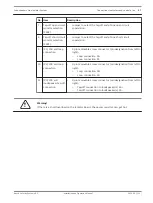
Warning!
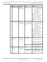
In Walk Test mode the Master Unit will correctly display the status of the loop. The loop will
not be redundant. Make sure to set the Walk Test mode to OFF.
Option B (install all Isolator Boards and then check loop)
1.
Install the entire loop, by connecting all Isolator Boards and all DC Blocking Boards to the
Master Unit.
2.
Switch on the Master Unit.
3.
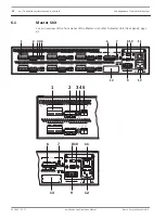
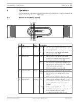
Set the loop to Walk Test mode, by setting the Walk Test DIP switch (5) on the Master
Unit to on.
4.
Check the loop OK LED indication (3) on the rear panel of the Master Unit.
5.
If the loop OK LED (3) is on, the connection is correct.
6.
If the loop OK LED (3) does not light up:
–
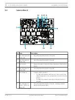
Check the test button (3) and LED indicator (5) on each Isolator Board as described
in option A.
–
Alternatively turn on the public address/voice alarm system and broadcast audio,
then perform a walk test in the loop to determine at which point the audio stops.
7.
After rectifying the problem, recheck the system.
8.
Set the Walk Test mode to off.
See also
–
40
en | Connections indicators and controls
Loudspeakers Line Isolator System
2014.03 | V1.1 |
Installation and Operation Manual
Bosch Security Systems B.V.