10.7
Bearing and shaft load
10.7.1
Radial load, axial load
During operation, radial and axial forces act on the motor shaft and the motor
bearings. The design of the machine, the selected motor type and the shaft-
side mounting of drive elements must be coordinated to ensure that the
specified load limits are not exceeded.
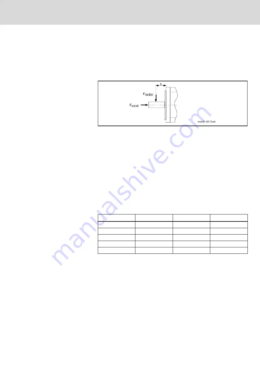
x
Point of application of force
Fig. 10-6:
Example diagram of shaft load
Maximum allowed radial force
The maximum permissible radial force F
radial_max
depends on the following
factors
●
Shaft breaking load
●
Force action point x
●
Shaft plain or with keyway
Permissible radial force
The permissible radial load F
radial
depends on the following factors
●
Arithmetically averaged speed (n
average
)
●
Force action point x
●
Bearing service life
Permissible axial force
The maximum permissible axial force F
axial
for the individual motor sizes is
shown in the following table.
Motor
F
axial
[N]
Motor
F
axial
[N]
MSK030
0
MSK070
60
MSK04x
30
MSK071
60
MSK050
40
MSK076
60
MSK060
40
MSK100
80
MSK061
40
MSK101
80
Tab. 10-7:
Maximum permissible axial force F
axial
Axial forces are permissible without restriction up to the specified values.
Larger axial forces may be possible after detailed examination by your
Rexroth sales partner. Specify the following information for the valuation:
●
Axial and radial force with force application point
●
Installation position (horizontal, vertical with the shaft end pointing to the
top or bottom)
●
Average speed
Average speed
Run-up and braking times can be omitted from the calculation if the time dur‐
ing which the drive is operated at constant speed is considerably longer than
the acceleration and braking times. In the exact calculation of the average
speed according to the following pattern, acceleration and braking times are
taken into account.
DOK-MOTOR*-MSK*EXGIIK3-PR09-EN-P
Bosch Rexroth AG
125/175
Synchronous Servomotors MSK For Potentially Explosive Areas
Operating conditions and application notes


