background image

MBE Mounts and Adapters

Attaching Cameras to the Brackets | en

19

Bosch Security Systems, Inc.

Installation Guide

 | 3.0 | 2011.10

4.

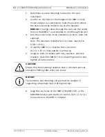
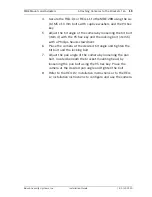
Secure the REG-D1 or REG-L1 to the MBE-28B using the six 

(6) M5 x 10 mm bolts with captive washers and the #4 hex 

key. 

5.

Adjust the tilt angle of the camera by loosening the tilt bolt 

(item 4) with the #5 hex key and the locking bolt (item 5) 

with a Phillips head screwdriver.

6.

Place the camera at the desired tilt angle and tighten the 

tilt bolt and the locking bolt.

7.

Adjust the pan angle of the camera by loosening the pan 

bolt, located beneath the bracket mounting head, by 

loosening the pan bolt using the #5 hex key. Place the 

camera at the desired pan angle and tighten the bolt. 

8.

Refer to the 

REG-D1 Installation Instructions 

or to the 

REG-

L1 Installation Instructions

 to configure and use the camera.

Summary of Contents for MBE Series

Page 1: ...MBE Mounts and Adapters MBE Series en Installation Guide ...

Page 2: ......

Page 3: ...unts and Adapters 6 2 1 Unpacking 6 2 2 Parts Lists 7 3 MBE 27 28 Wall Mount Applications 8 3 1 Mounting the MBE 27 28 to a Wall 8 3 2 Mounting the MBE 27 28 with the MBE 17 Wall Adapter 9 4 MBE 27 28 Pole Mount Applications 12 5 Attaching Cameras to the Brackets 15 5 1 Attaching an EX27 to the MBE 27 15 5 2 Attaching a REG D1 L1 to an MBE 28 17 6 Dimensional Outlines 20 ...

Page 4: ...rdous situation such as Dangerous Voltage inside the product If not avoided this will result in an electrical shock serious bodily injury or death WARNING Medium risk Indicates a potentially hazardous situation If not avoided this could result in minor or moderate bodily injury CAUTION Low risk Indicates a potentially hazardous situation if not avoided this could result in property damage or risk ...

Page 5: ...ified in the operating instructions 4 Unless qualified do not attempt to service a damaged unit yourself Refer all servicing to qualified service personnel 5 Use only replacement parts specified by the manufacturer 6 Install in accordance with the manufacturer s instructions in accordance with applicable local codes 7 Use only attachments accessories specified by the manufacturer Equipment change ...

Page 6: ... Bracket MBE 17B MBE 17W a black or white adapter used to attach an MBE 27 or an MBE 28 along with an EXMB 020B Heavy Duty L Bracket to a wall This adapter can also accommodate the EXMB 028 Cable Managed Wall Bracket or the EXMB 023 Wall Bracket Refer to Section 6 Dimensional Outlines page 20 for dimensional drawings of each mount and adapter 2 1 Unpacking This equipment should be unpacked and han...

Page 7: ...Pole mount adapter plate black or white 2 Metal bands with gear clamps 4 M6 x 20 mm bolts 4 M6 flat washers Quantity Description 1 Wall mount adapter plate black or white 4 M6 x 20 mm bolts 4 M6 flat washers Quantity Description 1 Bracket arm for EX27 black or white 1 6 Hex Key 1 EX27 interface plate 1 M8 x 45 mm bolt Quantity Description 1 Bracket arm for REG D1 REG L1 black 1 4 hex key 1 5 hex k...

Page 8: ...ide If studs are used they should either be anchored in concrete or welded to a steel backer plate 3 1 Mounting the MBE 27 28 to a Wall The MBE 27 28 can be mounted directly to a wall surface and can support up to 25 kg 55 lbs Use the MBE 17 wall mount adapter if your application requires extra support Refer to Section 3 2 Mounting the MBE 27 28 with the MBE 17 Wall Adapter page 9 1 Determine a se...

Page 9: ...nting location for the EXMB 020B L bracket a heavy duty bracket used to mount an additional piece of equipment such as an illuminator The combination of the MBE 27 28 and the MBE 17 can support a total weight of 45 kg 100 lbs Note The MBE 17 Wall Mount Adapter has two distinct hole patterns for attaching various mounting brackets Use the 94 2 x 40 mm 3 71 x 1 57 in hole pattern with the MBE 27 28 ...

Page 10: ...es in the installation location bolts not supplied Note The minimum diameter bolt or stud required is 6 mm 25 in 4 Orient the MBE 17 so that the 94 2 x 40 0 mm 3 71 x 1 57 in hole pattern is at the top 5 Using six bolts or studs with nuts washers and lock washers fasten the MBE 17 to its mounting location and tighten all nuts securely 6 Align the four holes on the MBE 27B MBE 27W or the MBE 28B br...

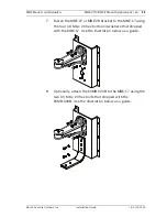
Page 11: ...10 7 Fasten the MBE 27 or MBE 28 bracket to the MBE 17 using the four 4 M6 x 20 hex bolts and washers that shipped with the MBE 17 Use the illustration below as a guide 8 Optionally attach the EXMB 020B to the MBE 17 using the two 2 M6 x 20 hex bolts that shipped with the EXMB 020B Use the illustration below as a guide ...

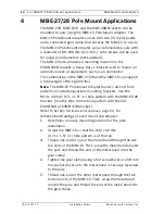
Page 12: ...e The MBE 15 Pole Mount Adapter has two distinct hole patterns for attaching various mounting brackets Use the 94 2 x 40 mm 3 71 x 1 57 in hole pattern with the MBE 27 28 bracket Use the 86 x 40 mm hole pattern with the old EXMB 023 or EXMB 028 bracket Refer to Section 6 Dimensional Outlines page 20 for dimensional drawings of each mount and adapter 1 Determine a secure mounting location for the p...

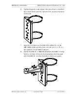
Page 13: ...mm hex socket driver until the metal band is securely fastened to the pole 7 Align the four holes on the MBE 27B MBE 27W or the MBE 28B bracket with the 94 2 x 40 mm 3 71 x 1 57 in hole pattern on the MBE 15 adapter 8 Fasten the MBE 27 or MBE 28 bracket to the MBE 15 using the four 4 M6 x 20 hex bolts and washers that shipped with the MBE 15 Use the illustration below as a guide ...

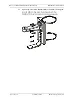
Page 14: ...ons MBE Mounts and Adapters 3 0 2011 10 Installation Guide Bosch Security Systems Inc 9 Optionally attach the EXMB 020B to the MBE 15 using the two 2 M6 x 20 hex bolts that shipped with the EXMB 020B Use the illustration below as a guide ...

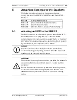
Page 15: ...n Manual located on the Bosch Security System Web site for complete camera details Bracket Compatible Cameras MBE 27B MBE 27W EX27 EX27N All Weather Cameras EX27D Desert Camera MBE 28B REG D1 REG L1 License Plate Cameras NOTICE Select a suitable location that protects the camera from accidental damage tampering and environmental conditions that exceed the camera s specifications CAUTION The select...

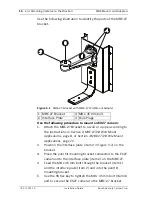
Page 16: ...n Section 3 MBE 27 28 Wall Mount Applications page 8 or Section 4 MBE 27 28 Pole Mount Applications page 12 2 Position the interface plate item 2 in Figure 5 1 on the bracket 3 Place the pan tilt mounting bracket connected to the EX27 camera onto the interface plate item 2 on the MBE 27 4 Feed the M8 x 45 mm bolt through the bracket item 1 and the interface plate item 2 and into the pan tilt mount...

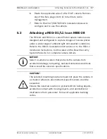
Page 17: ...nge of ambient light and weather conditions Refer to the REG D1 Installation Instructions or to the REG L1 Installation Instructions both located on the Bosch Security System Web site for complete camera details NOTICE Select a suitable location that protects the camera from accidental damage tampering and environmental conditions that exceed the camera s specifications CAUTION The selected mounti...

Page 18: ...h the MBE 28B Bracket to a wall or a pole according to the instructions in Section 3 MBE 27 28 Wall Mount Applications page 8 or Section 4 MBE 27 28 Pole Mount Applications page 12 2 Route the cable attached to the REG D1 or REG L1 camera through the MBE 28B and into the wall or through one of the plugs to facilitate cable management 3 Align the six 6 inner screw holes on the REG D1 or REG L1 with...

Page 19: ...4 with the 5 hex key and the locking bolt item 5 with a Phillips head screwdriver 6 Place the camera at the desired tilt angle and tighten the tilt bolt and the locking bolt 7 Adjust the pan angle of the camera by loosening the pan bolt located beneath the bracket mounting head by loosening the pan bolt using the 5 hex key Place the camera at the desired pan angle and tighten the bolt 8 Refer to t...

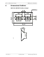
Page 20: ...Adapters 3 0 2011 10 Installation Guide Bosch Security Systems Inc 6 Dimensional Outlines MBE 15B MBE 15W Pole Mount Adapter 80 5 3 17 44 5 1 75 40 1 57 159 8 6 29 281 11 06 62 2 44 62 2 44 94 2 3 71 86 3 39 40 8 1 61 M6ThreadTyp12Places in mm ...

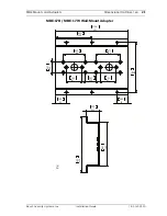
Page 21: ...utlines en 21 Bosch Security Systems Inc Installation Guide 3 0 2011 10 MBE 17B MBE 17W Wall Mount Adapter 40 1 57 281 11 06 42 1 65 42 1 65 140 5 5 53 194 7 64 86 3 39 94 2 3 71 62 2 44 62 2 44 40 8 1 61 168 6 61 48 3 1 90 218 8 58 in mm ...

Page 22: ...onal Outlines MBE Mounts and Adapters 3 0 2011 10 Installation Guide Bosch Security Systems Inc MBE 27B MBE 27W Bracket 233 50 9 193 102 4 016 40 1 568 94 17 3 708 122 95 4 841 69 2 717 Ø 5 8 2 2 8 3 207 8 150 in mm ...

Page 23: ...E Mounts and Adapters Dimensional Outlines en 23 Bosch Security Systems Inc Installation Guide 3 0 2011 10 MBE 28B Bracket in mm 90 3 54 73 4 2 89 171 4 6 75 233 5 9 19 94 17 3 708 40 1 57 73 2 87 63 2 48 ...

Page 24: ...24 en Dimensional Outlines MBE Mounts and Adapters 3 0 2011 10 Installation Guide Bosch Security Systems Inc ...

Page 25: ......
Page 26: ...Bosch Security Systems Inc 850 Greenfield Road Lancaster PA 17601 U S A www boschsecurity com Bosch Security Systems Inc 2011 ...

Reviews: