background image

LTC 8600 | LTC 8800 Series

en | 25

F.01U.127.393 | 2.0 | 2009.03

Instruction Manual

Bosch Security Systems, Inc.

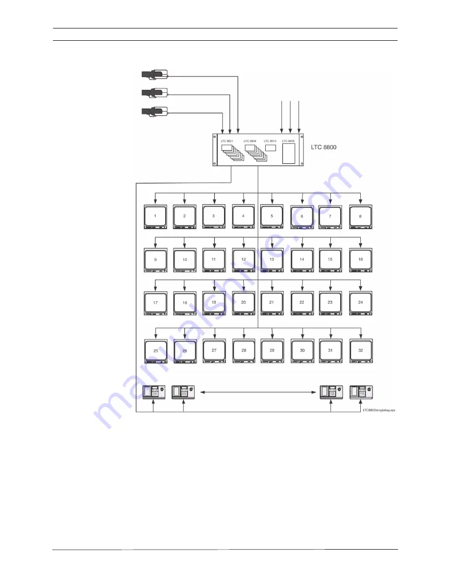
LTC 8800 Series Single Bay System (256 by 32 Configuration)

Figure 2: LTC 8800 Series Single Bay Video Switching Configuration

Main CPU Bay

Supports up 
to 32 Monitor Out-
puts

Maximum of 32 Allegiant 
Keyboards, up to 1.5 km (5000 ft) 

away using Optional 
Remote Hookup Kit

Supports up to 64 Video 
Inputs

Summary of Contents for LTC 8808/00 Series

Page 1: ...EN Instruction Manual Allegiant Microprocessor based Video Switcher Con trol Systems CPU Firmware Version 10 0 LTC 8600 LTC 8800 Series ...

Page 2: ......

Page 3: ...8569 LTC 8570 LTC 8571 LTC 8572 Series Code Merger Units 19 7 11 LTC 8770 Switcher Follower Series 19 7 12 LTC 8712 Series Console Port Expander Units 19 7 13 LTC 8713 Alarm Port Expander Units 19 7 14 LTC 8714 LTC 8715 Series Keyboard Port Expander Units 19 7 15 LTC 8780 Series Data Converter Units 20 7 16 LTC 8781 Series Data Converter Units 20 7 17 LTC 8016 90 Bilinx Data Interface Unit 20 7 18...

Page 4: ...Line Monitor Outputs 36 10 2 Main Site Trunk Line Video Inputs 37 10 3 Control Data Lines in Satellite Systems 37 10 4 Satellite Site Programming Requirements 37 10 5 Main Site Programming Requirements 38 10 6 Special Programming for Cascaded Satellite System Configurations 40 10 7 Alarm Inputs in Satellite Systems 41 11 Feature Selection 42 12 Main Power Connections 43 13 Video Monitor Display 45...

Page 5: ...on 59 16 6 Sample Alarm Responses 59 16 7 Alarm Relay Response 61 17 Keyboard Operation 62 17 1 General 62 17 2 System Commands 62 17 2 1 Keyboard Log in Procedure 62 17 2 2 Keyboard Log off Procedure 63 17 3 Switcher Commands 63 17 4 Controlling Camera Movement 63 17 4 1 Focus and Iris Lens Control 63 17 4 2 Lock or Unlock Control of a Camera 63 17 4 3 Lock or Unlock Control of a Monitor 64 17 4 ...

Page 6: ... 20 Character ROM Tables for LTC 8600 and LTC 8800 86 21 ERROR MESSAGES 99 22 Troubleshooting Guide 102 22 1 Main Bay Checkout 102 22 2 Keyboard Checkout 103 22 3 Video Monitor Display Checkout 103 22 4 Remote Receiver Driver Functions Inoperative 104 22 5 No Alarm Response 104 22 6 CPU Software Version Numbers 104 23 GLOSSARY OF TERMS 105 Appendix A Satellite Systems 107 Appendix B Installation C...

Page 7: ... any kind into this unit through openings as they may touch dangerous voltage points or short out parts that could result in a fire or electrical shock Never spill liquid of any kind on the unit Do not place objects filled with liquids such as vases or cups on the unit 6 Lightning For added protection during a lightning storm or when leaving this unit unattended and unused for long periods unplug ...

Page 8: ...ervice Unplug the unit from the main AC power source and refer servicing to qualified service personnel when any damage to the equipment has occurred such as the power supply cord or plug is damaged exposure to moisture water and or inclement weather rain snow etc liquid has been spilled in or on the equipment an object has fallen into the unit unit has been dropped or the unit cabinet is damaged ...

Page 9: ...Any output or signal lines from the camera must be SELV or Limited Power Source For safety reasons the environmental specification of the camera lens assembly must be within the environmental specification of 10 C 14 F to 50 C 122 F Camera signal Protect the cable with a primary protector if the camera signal is beyond 140 feet in accordance with NEC800 CEC Section 60 Coax grounding Ground the cab...

Page 10: ...tion must be secured with a maximum fuse rating of 16A This must be in accordance with NEC800 CEC Section 60 Grounding and polarization This unit may be equipped with a polarized alternating current line plug a plug with one blade wider than the other blade This safety feature allows the plug to fit into the power outlet in only one way If unable to insert the plug fully into the outlet contact a ...

Page 11: ...adio frequency energy and if not installed and used in accordance with the instruction manual may cause harmful interference to radio communications Operation of this equipment in a residential area is likely to cause harmful interference in which case the user will be required to correct the interference at his expense Intentional or unintentional modifications not expressly approved by the party...

Page 12: ...fire shock and or casualty hazards as outlined in UL s Standard s for Safety for Closed Circuit Television Equipment UL 2044 UL Certification does not cover the performance or reliability of the security or signaling aspects of this product UL MAKES NO REPRESENTATIONS WARRANTIES OR CERTIFICATIONS WHATSOEVER REGARDING THE PERFORMANCE OR RELIABILITY OF ANY SECURITY OR SIGNALING RELATED FUNCTIONS OF ...

Page 13: ...ort Telephone 800 326 1450 Fax 585 223 3508 or 717 735 6560 E mail technical support us bosch com Canada Telephone 514 738 2434 Fax 514 738 8480 Europe Middle East Africa Region Repair Center Telephone 31 0 76 5721500 Fax 31 0 76 5721413 E mail RMADesk STService nl bosch com Asia Region Repair Center Telephone 65 63522776 Fax 65 63521776 E mail rmahelpdesk sg bosch com Customer Service Telephone 8...

Page 14: ...8 LTC 8600 LTC 8800 Series F 01U 127 393 2 0 2009 03 Instruction Manual Bosch Security Systems Inc ...

Page 15: ...If any items are missing notify your Bosch Secu rity Systems Sales or Customer Service Representative The original packing carton is the safest container in which to transport the unit Save it for possible future use 2 1 Parts List The following table lists the components Qty Item 1 LTC 8601 Series or LTC 8801 Series Main CPU card cage 1 LTC 8610 01 CPU module or LTC 8810 01 CPU module 1 LTC 8805 ...

Page 16: ...3 9180 E mail security sales us bosch com Technical Support Telephone 800 326 1450 Fax 585 223 3508 or 717 735 6560 E mail technical support us bosch com Canada Telephone 514 738 2434 Fax 514 738 8480 Europe Middle East Africa Region Repair Center Telephone 31 0 76 5721500 Fax 31 0 76 5721413 E mail RMADesk STService nl bosch com Asia Region Repair Center Telephone 65 63522776 Fax 65 63521776 E ma...

Page 17: ... LTC 8540 00 Alarm Interface unit an external con tact closure or logic level can be used to automatically display any camera Any mon itor or group of monitors can be set to display cameras under alarm conditions The base system contains three 3 built in alarm response modes basic auto build and sequence and display In addition to these three 3 modes the PC based soft ware packages offer the abili...

Page 18: ...he PC screen and if desired logged to the PC hard drive The LTC 8850 00 GUI Software can also be used to enable a special on screen icon for identifying controllable cameras The CPU inside these matrix switchers supports powerful macro capabilities The macros can be activated using system keyboards system time event functions alarm activations and via special function icons in the LTC 8850 00 GUI ...

Page 19: ...e sequences Y Y 8 Alarm call up of pre position scenes Y Y 9 RS 232 Interface ports for computer logging printer etc Y Y 10 Keyboard log on log off function Y Y 11 User selectable password security Y Y 12 16 Character camera titles and 12 character monitor titles Y Y 13 User selected 40 character camera titles using third line of on screen text Y N 14 User selectable 2 digit site plus 4 digit came...

Page 20: ...232 serial printer or some other form of logging software can be used to capture log data This provides a permanent record showing time and date of changes to system status such as Incoming alarms Acknowledgment of alarms by users Loading sequences User log on to keyboard or console port Console broadcast message Console transfer of system tables Activation of time event functions Power up reset m...

Page 21: ...puts Satellite configuration input capacity 1152 6 2 LTC 8800 Series Systems LTC 8801 Series Main CPU Bay A modular equipment bay which contains the system s microprocessor module LTC 8810 01 the power supply module LTC 8805 Series and several video input and video output modules see below LTC 8802 Series Monitor Expansion Bay A modular equipment bay which contains a Data Receiver module LTC 8816 ...

Page 22: ...utput modules four 4 outputs per module Subtotal 256 inputs and 32 outputs on main bay Monitor Expansion Bay Up to eight 8 video input modules duplicating modules on main bay Up to eight 8 extra output modules providing four 4 additional outputs each Subtotal 32 extra outputs added on to the main bay s outputs Total 256 maximum inputs 64 maximum outputs Satellite configuration input capacity 2304 ...

Page 23: ...bution and line driver units are available for communicating to receiver drivers switcher followers and Alle giant Satellite systems The LTC 8568 00 Signal Distribution Unit provides 32 sepa rate outputs for driving up to 256 remote devices Either star or daisy chain wiring configurations may be used The LTC 8768 00 Signal Distribution unit is sim ilar to the LTC 8568 00 except that it provides 64...

Page 24: ...rface kit used to remote the IntuiKey Series or LTC 8555 Series keyboards up to 1 5 km 5000 ft away from the main CPU bay Customer supplied 0 5 mm2 24 AWG shielded twisted pair Belden 9841 or equivalent required between the main CPU bay site and keyboard site Kit provides two 2 junction boxes interface cable and appropriate keyboard power supply 7 8 LTC 8560 and LTC 8561 Series Receiver Driver Uni...

Page 25: ...ur external computing devices to communicate with the system via RS 232 proto col Any computing device that can normally communicate directly with an Allegiant via its RS 232 console port can be used with these port expanders The external devices may consist of PCs running the Allegiant system s MCS package the Alle giant GUI access control systems Allegiant RS 232 protocol keyboards or other devi...

Page 26: ...ameras The LTC 8016 provides complete control of pan tilt zoom auxilia ries and pre position functions of Bilinx enabled AutoDome Series cameras In addition complete programming of Dinion Series cameras and AutoDomes via their on screen menus is supported Bilinx technology also supports camera generated event reporting to the Allegiant This connection allows remote alarm inputs and motion event da...

Page 27: ...d compatible computer this software is the human interface that makes it quick and easy to configure an entire Allegiant system With the MCS package users can set and change an Allegiant s system parameters program camera sequences lock cameras monitors remotes and keyboards from certain users and perform many other system control features Users can also view system activity with real time monitor...

Page 28: ...SDK is a fully supported set of libraries documentation and samples targeted at PC based application software that is used to control 3rd party CCTV matrix systems or manage IP based digital video networks Since the SDK can be used to create customized solutions for unique specific problems customers looking to integrate an Allegiant matrix sys tem with products offered by other manufacturers is r...

Page 29: ...o 16 channels of video signals from digital video recorders such as the Divar Dibos and DesaXL or other BNC equipped devices to the ribbon cable con nectors located on the rear panels of the LTC 8600 and LTC 8800 Series bays 7 26 Logging Printer An optional RS 232 serial printer may be connected to these systems to provide a permanent record of significant system status changes Time and date is pr...

Page 30: ... 393 2 0 2009 03 LTC 8600 Series Video Switching System Figure 1 LTC 8600 Series Basic Video Switching Configuration Maximum of 16 Allegiant Keyboards up to 1 5 km 5000 ft away using Optional Remote Hookup Kit Main CPU Bay Supports up to 128 Video Inputs Supports up to 16 Monitor Outputs ...

Page 31: ... Inc LTC 8800 Series Single Bay System 256 by 32 Configuration Figure 2 LTC 8800 Series Single Bay Video Switching Configuration Main CPU Bay Supports up to 32 Monitor Out puts Maximum of 32 Allegiant Keyboards up to 1 5 km 5000 ft away using Optional Remote Hookup Kit Supports up to 64 Video Inputs ...

Page 32: ...tem 256 by 64 Configuration Figure 3 LTC 8800 Series Dual Bay Video Switching Configuration Supports up to 256 Video Inputs Coax Ribbon Jumper Cables Supplied Supports up to 64 Monitor Outputs Maximum of 32 Allegiant Keyboards up to 1 5 km 5000 ft away using Optional Remote Hookup Kit Control Data Monitor Expansion Bay Main CPU Bay ...

Page 33: ...arm Inputs Maximum Up to 256 Receiver Driver Units Up to 1 5 km 5000 ft using 18 g Shielded Twisted Pair Cable Belden 8760 or Equiv Serial Logging Printer Capability 12 VDC LTC 8808 Interconnect Panel Video Ribbon Jumper Cables Supplied with LTC 8802 Port Expander Accessories Keyboard Expander Units used for System Keyboards above 16 Monitor Expansion Bay can Operate up to 8 Keyboards LTC 8540 Ala...

Page 34: ...ack remove the four 4 rubber bumper foot pads found on the bottom of the bay before install ing the unit in the rack Four 4 holes are provided for mounting the bay s in the rack If any LTC 8802 Series Monitor Expansion bay is supplied it should be located as close as possible to the LTC 8801 Series Main CPU bay to facilitate cable interconnections 5 Install the LTC 8600 Series the LTC 8800 Series ...

Page 35: ...Insertion If the LTC 8802 Series Monitor Expansion Bay is being used it should be loaded with VIMs in the same fashion The Main CPU Bay should be FULLY loaded with 8 output modules before putting output modules into the Monitor Expansion Bay Remaining output modules are inserted into the Monitor Expansion Bay starting at slot 9 If fewer than the maximum number of outputs are being used the Monitor...

Page 36: ...onitor to video out put 1 The video outputs are the left most column of BNC connectors on the rear of the bay Use only those outputs that correspond to an installed Video Output Module VOM 8 5 1 LTC 8600 Series and LTC 8800 Series Video Input Connections The LTC 8601 Series and the LTC 8801 Series main bays have 96 direct BNC connectors available for video input Cameras above 96 require the use of...

Page 37: ...arately for each group of 32 cam eras above 96 that will be connected to an LTC 8800 Series system Figure 8 Typical Use of LTC 8808 00 Video Interconnect Panel Install any supplied LTC 8808 00 Patch Panel on the rear of the racking equipment Note that additional VIMs ordered in the future may also require the use of LTC 8808 00 Patch Panels It is recommended to order the appropriate quantities at ...

Page 38: ...ful not to force the cables into the mating connectors backwards IMPORTANT The Termination DIP switches on the VIM cards installed in the main bay must be turned OFF This will make the main bay inputs non terminated and the expansion bay will provide the termination for the video inputs Figure 9 Typical LTC 8809 00 Cable Connections KEYBOARD VIDEO IN 1 3 5 7 2 4 6 8 CONSOLE ALARM PRINTER SDA COMM ...

Page 39: ...he LTC 8801 Series Main CPU bay and the Comm1 port on the LTC 8802 Series Moni tor Expansion Bay 8 6 4 Monitor Output Video Connections Just like camera inputs monitor outputs on the Allegiant system are designed to be terminated Each monitor output expects to be connected to a 75 ohm load This is the regular load typically provided by a normal monitor If a monitor output line is looped through se...

Page 40: ...cessary 3 Set any configuration switches for your particular printer to match the format provided by the Allegiant system Note that the system communication protocol can be changed using the Keyboard User Functions described later in this man ual or with the optional Allegiant LTC 8059 MCS package The factory default values are as follows NOTE The required interconnect cable utilizes a custom pino...

Page 41: ...legiant CPU bay connector marked Console or another port that has been configured to operate as a Console port 3 Attach the other end of the cable to an available serial port COMM PORT 1 or COMM PORT 2 on the rear of the computer 4 Apply power to the computer and allow it to boot up its operating system before inserting the software disc 5 Refer to the applicable Allegiant software manual for comp...

Page 42: ...ge from 1 to the maximum number of monitor outputs provided by the switcher Note that the number of trunk lines coming from a satellite site determines the maximum number of cameras from that site which may be viewed simultaneously at the main site If operators will be stationed at the satellite site they should be prevented from accessing the monitor outputs designated as trunk lines This prevent...

Page 43: ...cted to a LTC 8780 Series Data Converter unit which provides address decoding functions for the sat ellite site An LTC 8780 Series is required for each satellite site and must be given a unique site address number If operators stationed at the satellite site are permitted to control pan tilt zoom equipped cameras an LTC 8569 Series Code Merger unit must be installed at the satellite site In order ...

Page 44: ...DIP Switch S2 is set to the ON position 10 5 Main Site Programming Requirements At the main site the Camera ID Table must be programmed to ensure proper satel lite operation It is easiest to start with the trunk line inputs For each trunk line the satellite s monitor output number and its bay address must be entered same num ber as the satellite s LTC 8780 address Camera numbers should be programm...

Page 45: ...ected to display a local camera via the system keyboard This prevents unused monitor outputs from using up trunk lines which may result in some confusing operational responses The Start up camera numbers listed in the Monitor Table of the LTC 8059 00 soft ware should be programmed to specify locally connected cameras or a local unused input i e the raster generator will be displayed when called up...

Page 46: ... the intermediate level system For the monitors being used as trunk lines in the intermediate system it is important for the Start up camera numbers listed in the Monitor Table of the LTC 8059 00 software to be programmed to specify cameras connected locally or a local unused input i e the raster generator will be displayed when called up This action ensures that no trunk line is used when a monit...

Page 47: ...eo at the main site If the application requires alarms located at a satellite to activate video at the main site the remote alarms must be brought back to the main site If necessary the main site s LTC 8540 00 Alarm Interface unit can be remotely located via an RS 232 link Since the Alarm Interface capability is an integral part of the LTC 8100 LTC 8200 and LTC 8300 Series this is not possible if ...

Page 48: ...lection Certain user selectable features can provide enhanced Allegiant system operation capabilities Any desired changes can be made now or delayed until specific system requirements become more apparent Refer to the Factory Default Settings Section for a full description of these features and selection instructions ...

Page 49: ... the system monitors may momentarily display video output module software version information Installations having cameras powered from an AC phase different than that of the Allegiant system may utilize the built in EXTERNAL SYNC input or vertical PHASE ADJUST NOTE All cameras should be phased properly with each other before the EXTERNAL SYNC or PHASE ADJUST feature is implemented The EXTERNAL SY...

Page 50: ...struction Manual F 01U 127 393 2 0 2009 03 Figure 15 LTC 8808 00 Video Interconnect Panel Figure 16 LTC 8801 Series Main CPU Bay Rear Panel Figure 17 LTC 8802 Series Monitor Expansion Rear Panel C ONS OL E A L A R M P R INT E R S D A C OMM P OR T2 A UX IL IA R Y ...

Page 51: ...enerated by the system CPU microprocessor module It is crystal controlled and battery protected for one year minimum without power The display is updated once per second and all monitors update simultaneously The time date message is always on the right side of the video display with the time on the top line Time displays hours minutes and seconds and can be set to either 12 hour or 24 hour operat...

Page 52: ...e pressing NEXT RUN or PRE VIOUS on the keyboard will move you through the alarm sequencer rather than the regular camera sequencer The alarm switcher status will be displayed in location 6 using described symbols 13 2 3 Location 4 Monitor Arm Status Indication In the MONITOR ARMED location the characters SM or DM will appear if the moni tor is armed for alarm SM means that the monitor is a step o...

Page 53: ... user error has occurred this location will temporarily hold part of the error number 13 2 7 Location 8 Monitor Lock Indication This location will display characters ML to indicate that the monitor has been locked by a user The camera currently being viewed can not be changed except by the user who locked the monitor or one with higher priority If the monitor is not locked the icon will not be dis...

Page 54: ...tware package Table 1 Format of Monitor Overlay s System Status Display 13 4 Broadcast Message The operator of the personal computer can send a message using the optional LTC 8059 00 MCS package or the optional LTC 8850 00 GUI Software package to all the monitors in the system This message may be up to 24 characters long and can be used to notify all users at all monitor locations of important inf...

Page 55: ...era Title The camera identification display is the first 16 characters of the lower line These 16 characters label each camera Each camera has its own title which is displayed whenever that camera is called up for viewing The characters can be entered from the keyboard see User Function 9 or may be entered from the personal computer keyboard using the optional LTC 8059 00 MCS package or the option...

Page 56: ...sole Port Expander is connected to the Allegiant s console port This selection can also be set using either the MCS or the PC based GUI Software package Switch 4 of S1 Use this switch to set the communication baud rate that the Allegiant will use when connected to a LTC 8712 Series Console Port Expander It is only applica ble when DIP switch 3 is in the ON position When set to ON the baud rate wil...

Page 57: ...hen interfacing with the alarm port If necessary See Chapter Appendix D Main Bay Rear Panel Connector Pin outs on page 117 for the alarm port pin outs Switch 3 of S2 This switch setting is ignored if DIP switch 7 described below is set to ON Current systems utilize a variable speed keyboard communication protocol Older systems and keyboards were limited to using fixed speed keyboard communication ...

Page 58: ...this switch is set to ON the system log in features can be controlled using keyboard User Function 27 and User Function 28 refer to the section on Keyboard User Functions for com plete information Users with Priority 1 can access keyboard User Function 27 to select if the system keyboard log in feature is enabled or disabled When enabled the system keyboards require each user to log in to the syst...

Page 59: ...he higher preposition numbers in current versions of Allegiant receiver drivers Switch 8 of S2 This switch controls the protocol settings of the external RS 232 port which connect to the Console Printer and Alarm If the switch is turned OFF the system uses the factory default settings for the RS 232 data communication protocols as listed below With switch 8 ON any RS 232 port protocols changed usi...

Page 60: ...nctions Switch 1 of S1 This switch selects the frequency of the internal raster generator used for dis play of on screen text during video loss conditions When set to OFF the raster is generated at 60 Hz default for 120 VAC models When ON the raster is gen erated at 50 Hz default for 220 240 VAC models To set the DIP switch changes power the unit OFF and then turn the unit ON Switch 2 3 and 4 of S...

Page 61: ...l This format is required to provide variable speed pan tilt control capability for AutoDome equipped camera sites If it is necessary to communicate to older system key boards that are only compatible with fixed speed keyboard protocols place the switch in the OFF position Switch 7 of S2 This switch determines the operational mode of the LTC 8816 00 and must always be left ON Switch 8 of S2 This s...

Page 62: ... optional LTC 8059 00 MCS package or the optional LTC 8850 00 GUI Software package Note that in base systems where the keyboard log in feature has not been selected a user number is automatically assigned to a specific keyboard port In this mode setting the priority of the default user essentially determines the priority level of the keyboard during operation Also shown in the table is the default...

Page 63: ...Acknowledge Alarms Yes Yes Yes Perform Keyboard Test Yes Yes Yes Show Keyboard Number Yes Yes Yes Activate Keyboard Beeper Yes Yes Yes Change User Password Yes Yes Yes Program Sequences Yes Yes No Position Video Overlay Display Yes Yes No Set Overlay Display Brightness Yes Yes No Select Overlay Display Type Yes Yes No Set System Time Date Yes Yes No Program Pre positions Yes Yes No Set Time Date F...

Page 64: ...ses a set of monitors as alarm display monitors All system monitors may be armed if desired Each triggered alarm will display its alarm video on a dif ferent monitor starting with the lowest numbered armed monitor If all the armed monitors are already displaying alarm video subsequent alarms will build on the existing alarmed monitors and each monitor will sequence through its alarm videos at a 1 ...

Page 65: ... on monitors are sequenced automatically Alarmed video remains on monitors for duration of alarm input signal Auto Build Mode In the Auto Build alarm response mode alarms build up on armed monitors as new alarms are received Any number of monitors may be armed Multiple alarms on monitors are sequenced automatically Alarm video remains on monitors for duration of alarm input signal Alarm Status Ala...

Page 66: ...ted with 1st alarm is displayed NONE 2nd Alarm Occurs S Video associated with 1st and 2nd alarm is displayed D Video associated with 1st alarm is displayed NONE 3rd Alarm Occurs S Video associated with 1st 2nd and 3rd alarm is displayed D 1st alarm video is removed 2nd alarm video is now displayed 1st Alarm Acknowledged S Video associated with 2nd and 3rd alarms continue to sequence D 2nd alarm vi...

Page 67: ...system operator s from all system monitors Relay 1 also deactivates if the system is disarmed either the monitor or the alarm s by an operator via the keyboard Removal of the alarm input does not deactivate Relay 1 since the alarm video s are not dependent on duration of the contact applied to the unit in this alarm response mode Other relays are not used in this mode 3 If the base system uses the...

Page 68: ...ser number and password Up to 32 user numbers are available each having default priority level User specific priority levels can be changed only via the optional PC based LTC 8059 00 MCS package or the LTC 8850 00 GUI Soft ware Refer to the software manual for complete details If the log on feature is enabled and an operator is not logged in LED keyboards show flashing dashes in their display Intu...

Page 69: ...moves the camera in a diagonal direction Rotate the joystick knob to control the zoom lens in or out The direction of its response depends on the camera lens model and certain system configuration set tings that are determined at installation Up to four pan tilt zoom commands may be sent to a remote camera site at a time Example Zoom In Focus Far Pan Left and Tilt Down All three 3 zoom lens functi...

Page 70: ... tion manual for complete information If an Allegiant conventional receiver driver is being controlled the pan tilt and zoom lens must have the necessary options for pre position operation On certain models of AutoDomes and Allegiant Receiver Driver Series it is possible to disable a previously stored pre position or remove it from a pre position tour by pressing Set Shot Set the digit 9 followed ...

Page 71: ...enabled by an option switch in the receiver driver and is controlled by the auxiliary 5 function To activate the DITHER function turn ON auxiliary 5 To deactivate the feature turn OFF auxiliary 5 When first enabled the pan tilt unit makes one short left right cycle to indicate that the DITHER function has been activated Note that a camera in the DITHER mode will accumulate a viewing error if left ...

Page 72: ...rmed 17 5 4 Alarms Acknowledgement Bell Ack is provided so system operators can respond to alarms from the keyboard Press Bell Ack when the keyboard is beeping due to an alarm condition to silence the beeper Depending on alarm configuration programming subsequent pressing of Bell Ack either clears an alarm video from the monitors or has no effect 17 6 Sequence Control 17 6 1 Load Clear a Sequence ...

Page 73: ...e to manually step forward or reverse through a stopped sequence These actions work as follows If Next Sequence Step Next is pressed with the sequence in the stop state the sequence switches forward and remains stopped If the sequence is running when Next Sequence Step Next is pressed it immediately goes to the next step and con tinues to run The same is true for the Previous Sequence Step Prev bu...

Page 74: ...hen programming a new sequence the camera number that was being viewed before entering the programming mode is automatically placed between the prompts as in the example C0001 above Now enter the 1st camera of the sequence into this position If 6 digit camera ID mode is enabled five or six digits must be entered If the camera number is correct no action is necessary If not enter the desired camera...

Page 75: ...g a new line and press Insert Step ON A new line identical to the one you are on is added to the next step To delete a step navi gate to the line to be deleted and press Delete Current Step OFF To delete all steps below the line you are viewing press Delete From Here To End Lock Be careful with this feature It is also possible to erase a sequence Press Delete From Here To End Lock while on the fir...

Page 76: ...monitor An example of a simple Salvo sequence that switches cameras on three 3 monitors simultaneously is shown below In general follow the instructions used for the simple camera sequence described above but instead of entering a number of seconds for steps that must switch instantly enter 61 and press Enter This causes the switcher to automatically change to the salvo abbreviation SLV Dwell time...

Page 77: ...the following procedure 1 From the main Allegiant screen press User Functions softkey 2 Use Previous or Next to navigate to the desired function or press the Enter User Command key and enter the desired number 3 Press the desired softkey For LTC 8555 Series keyboards User Functions are accessed using the following procedure 1 Press User and verify the indicator lights 2 Using the numeric keypad en...

Page 78: ...ect n a Select control code format fixed variable Y N N 23 n a n a Display CPU software version number Y Y Y 24 Up Down Left Right Set positions on all monitor displays Y Y N 25 Brightness Msg vs Stat Brightness Status select on all monitor displays Y Y N 26 Time Date Overlay Set display option on all monitors Y Y N 27 Keyboard Log in Select Select keyboard log in Y Y N N 28 Console Log in Select ...

Page 79: ...ensure that all keys are properly being processed by the keyboard Push USER last as this causes the keyboard to exit the test mode If the log on system feature has been selected by the system installer the same local test may be initiated while the keyboard is not ON LINE by pressing STAR 1 Keyboard tests show a speed indicator value in the first digit position when per forming pan tilt or zoom ac...

Page 80: ...us display or a 12 char acter monitor message to appear in the first line of the monitor display The status display indicates alarm sequence and lockout information regarding the monitor The monitor message is a stationary display This means the display will not change as video is switched from camera to camera on the monitor After entering the mode move the joystick left to select monitor message...

Page 81: ...n 10 is used to change an operator s keyboard log on access password This feature is only required in systems where the system installer has enabled the keyboard log in security feature After entering the mode the video monitor display prompts for the current password OLD PASSWORD Enter the current user pass word via the numeric keypad and press Enter If the system does not accept the old password...

Page 82: ...ter a 12 character monitor identification message for display in the top line of the monitor overlay display on any system monitor s This monitor title will be visible on the display regardless of the camera currently being viewed This message can be used to identify the particular monitor or a group of cameras assigned to this monitor See Chapter 20 Character ROM Tables for LTC 8600 and LTC 8800 ...

Page 83: ...Series keyboard press User to exit User Function 23 Display CPU Software Version Number Use this function to display the revision number of the Allegiant s CPU software on the monitor screen User Function 24 Set Positions on All Monitor Displays This function is similar to User Function 4 except it changes the monitor display positions of all monitors in the system After entering User Function 24 ...

Page 84: ...ion will be active and all system keyboards will need to be logged in to access the system User Function 28 Select Console Log in This function controls the system s external console port log in feature After enter ing the mode move the joystick up or down to select the mode in which the system should function If the log in feature is enabled MUST USE CON PWD is selected any external PC or other c...

Page 85: ...on is used to enable an onscreen indicator to identify a pan tilt equipped camera Move the joystick up or down to select DISP CAM CONTROL or NO CAM CONTL DISPL Press Enter to activate your selection When enabled cameras iden tified as controllable via User Function 35 or the optional LTC 8059 00 MCS pack age show a in the middle of the first line of monitor text User Function 35 Controllable Camer...

Page 86: ...ellite cameras are reselected It is not recommended for use in cascaded systems In cascaded systems this mode could result in all available trunk lines coming from the 3rd level satellite system to become used up making them unavailable to the opera tors at the intermediate system NO REM CAM CACHE option In this mode after the top level operator selects a locally connected camera the trunk line be...

Page 87: ...on An operator s monitor will use the same trunk from the same bay as different cameras are selected as long as no other operator is viewing the same satellite camera User Function 42 Keyboard Log in Auto off Mode Priority 1 users can use this function to select a keyboard log off feature to automat ically log a keyboard off after a pre selected time of inactivity After entering the mode move the ...

Page 88: ...hird party RS 232 serial interface utilizing the Allegiant Command Console Language CCL commands User Function 47 Six digit Camera ID Use this function to enable disable 6 digit Camera ID mode When enabled 2 digit site numbers are displayed in addition to the 4 digit camera number The 2 digit site number feature is especially useful when groups of cameras are located in separate buildings floors o...

Page 89: ... the plastic surfaces 19 2 AC Line Voltage Input Selection The AC line voltage input selector is found on the rear of the equipment bay inside the line cord connector housing The present input voltage selection will be shown in the window of the connector housing Remove AC line cord if the setting is incor rect To change the setting insert a flat blade screwdriver into the slot located at one end ...

Page 90: ...he equipment bay Remove the front panel of the bay by loosening the four fasteners Locate the fuse to be replaced by observing the green LED indicators Note which LED indicators are not lit then turn OFF the main power switch located on the power supply Replace fuses associated with LEDs which were not lit Switch on the main power switch and verify that all LEDs are now lit Replace front panel 19 ...

Page 91: ...on the front edge of the CPU card and are about 25 mm 1 in in diameter Insert a small flat blade screwdriver into the slot on one of the battery holder sockets and gently pry the battery from the holder until it can be removed by your fingers Replace old battery with new battery by lifting the retain ing clip up while inserting the battery into the socket Insure that the negative side of the batte...

Page 92: ...le on the following pages Note that in some cases a single character may be com prised of two 2 parts Such characters must be entered so that the left half of the character always begins in an odd numbered column of the display title The code numbers of these double width characters are shown in black boxes in the table below Refer to the section of the operating instructions covering User Functio...

Page 93: ...LTC 8600 LTC 8800 Series en 87 F 01U 127 393 2 0 2009 03 Instruction Manual Bosch Security Systems Inc ...

Page 94: ...88 en LTC 8600 LTC 8800 Series Bosch Security Systems Inc Instruction Manual F 01U 127 393 2 0 2009 03 ...

Page 95: ...LTC 8600 LTC 8800 Series en 89 F 01U 127 393 2 0 2009 03 Instruction Manual Bosch Security Systems Inc ...

Page 96: ...90 en LTC 8600 LTC 8800 Series Bosch Security Systems Inc Instruction Manual F 01U 127 393 2 0 2009 03 ...

Page 97: ...LTC 8600 LTC 8800 Series en 91 F 01U 127 393 2 0 2009 03 Instruction Manual Bosch Security Systems Inc ...

Page 98: ...92 en LTC 8600 LTC 8800 Series Bosch Security Systems Inc Instruction Manual F 01U 127 393 2 0 2009 03 ...

Page 99: ...LTC 8600 LTC 8800 Series en 93 F 01U 127 393 2 0 2009 03 Instruction Manual Bosch Security Systems Inc ...

Page 100: ...94 en LTC 8600 LTC 8800 Series Bosch Security Systems Inc Instruction Manual F 01U 127 393 2 0 2009 03 ...

Page 101: ...LTC 8600 LTC 8800 Series en 95 F 01U 127 393 2 0 2009 03 Instruction Manual Bosch Security Systems Inc ...

Page 102: ...96 en LTC 8600 LTC 8800 Series Bosch Security Systems Inc Instruction Manual F 01U 127 393 2 0 2009 03 ...

Page 103: ...LTC 8600 LTC 8800 Series en 97 F 01U 127 393 2 0 2009 03 Instruction Manual Bosch Security Systems Inc ...

Page 104: ...98 en LTC 8600 LTC 8800 Series Bosch Security Systems Inc Instruction Manual F 01U 127 393 2 0 2009 03 ...

Page 105: ...ss Restricted Monitor locked out by Monitor Lockout Table Error 10 Access denied A function was requested that requires a higher user priority Only a Priority 2 user or a supervisor with Priority 1 may access this function Error 11 Access denied A function was requested for which your user priority is too low Only a supervi sor with Priority 1 may access this function Error 15 Invalid user functio...

Page 106: ...ed Error 55 SEQUENCE priority The switcher sequence being requested or cleared requires monitors that are in use by a user of equal or higher priority Contact a user with higher priority or have the system administrator clear the monitors in question Error 56 SEQUENCE request The user has tried to load a sequence that is being edited in the PROGRAM mode Once editing is completed the sequence may b...

Page 107: ...d Check the appropriate section of the instruc tion manual for the desired operation and try again Error 92 Keyboard entry out of range The data entered for a valid command was not in the range allowed by the sys tem Check the appropriate section of the instruction manual for the acceptable ranges for the command in question and try again Error 94 Keyboard entry invalid An invalid character has be...

Page 108: ...tional Description Troubleshooting Information CPU ACT Random green blinking indicates normal CPU activity If always ON or always OFF the CPU is not functioning due to a serious problem with the CPU or the system power supply BATT LOW Lights red to indicate low or dead CPU battery condition Replace batteries per procedure described in Maintenance Information section TEMP CRIT Lights red to indicat...

Page 109: ...discrepancies are found replace keyboard 4 Keyboard Joystick not centered If the analog joystick of the system keyboard becomes un centered due to normal wear it can be re calibrated If using the IntuiKey keyboard go to the Keyboard Control menu and press Joystick Auto Calibrate If using the LTC 8555 Series keyboard refer to the User Function 1 procedure See Chapter 15 User Information on page 56 ...

Page 110: ...tors not responding when alarmed Ensure desired cameras are properly armed on the appropriate armed monitors in the system Verify alarming device and cable to Alarm Interface unit intact 3 Incorrect system alarm response Verify that the desired alarm response mode has been selected Refer to the section on Select User Functions for instruc tions 22 6 CPU Software Version Numbers During the evolutio...

Page 111: ...59 Master Control Software setups which can Restrict operators keyboards from viewing accessing any camera Restrict operators keyboards from controlling accessing any pan tilt Restrict operators from using certain keyboards Restrict operators keyboards from accessing certain monitors Log on Log off A selectable feature of the Allegiant system which requires operators to enter a User number and an ...

Page 112: ... functions such as monitor message broadcasts sequence and switching operations receiver driver actions message printing alarm settings and execution of custom factory programming can be stored in the system memory to be executed at a pre determined time The task can be specified to begin on a spe cific year month day and time and can be programmed to repeat at intervals rang ing from every five m...

Page 113: ...e conventional type system In a satellite configuration the Main control site can view control any camera in the entire system but the remote satellite sites can only view control cameras associ ated with their own site Satellites may be configured to operate either indepen dently or with no local viewing control capability It is also possible to configure satellite systems where each site can vie...

Page 114: ...ands generated by the Main site switcher The control data line should be connected to a LTC 8780 Series Data Converter to provide address decoding functions for the satellite site If operators at the satellite site are permitted to control pan tilt zoom equipped cameras a Allegiant Satellite Allegiant Satellite Allegiant Satellite Allegiant Satellite Allegiant Master Allegiant Master Allegiant Mas...

Page 115: ... site System capacities are listed below Since Main site Allegiant Series switchers support access to a large quantity of remote satellite cameras they provide additional logical camera numbers for identi fying the location of the satellite camera inputs in the system These logical camera numbers can also include titles which would appear on the Main site s monitors for any remote cameras Since ea...

Page 116: ... normally except when limited by the number of available trunk lines The software automatically determines trunk usage depending on the priority level of operators currently viewing satellite cameras Alarm inputs applied at a satellite site will NOT activate alarm video at the Main site If the application requires alarms located at a satellite to activate video at the Main site the Main site s LTC...

Page 117: ...Camera Typical Allegiant Satellite Site Video Typical P T Z Camera Video Video Video Video Console Port Typical Fixed Cameras Biphase Control and Sat ellite Data 1 Biphase Date Line to each Remote Satel lite Site Typical System Monitors Local Video Only Incoming Video Trunk Lines from all Satel lite Sites Alarm Interface Unit Typical Alarm Input Con tact Activates Local Alarms Only Biphase Data Li...

Page 118: ...Control and Sat ellite Data Code Merger Unit Typical Biphase Data Lines to all Local P T Z Cameras Typical System Monitors Local and or Remote Video Video Trunk Lines Biphase Data Lines Between Sites Typical System Monitors Local and or Remote Video Video Video Video Biphase Data Biphase Data Code Merger Unit Data Converter Unit Typical IntuiKey Keyboard Biphase Control and Sat ellite Data Typical...

Page 119: ... Typical P T Z Camera Typical Allegiant Satellite Site 3 Biphase Data Console Port Biphase Data Video Video Console Port Biphase Data Biphase Data Biphase Data Video Code Merger Unit Data Converter Unit Data Converter Unit Typical Biphase Data Line to all Local P T Z Cameras Typical P T Z Camera Typical System Monitors Video from Sites 2 and 3 Typical System Monitors Video from all Sites Typical A...

Page 120: ...hen begin appropriate programming PROGRAMMING VIA SYSTEM KEYBOARD Enter system time User Function 7 and date User Function 8 Enter Camera ID titles User Function 9 and if desired adjust monitor overlay displays User Function 4 5 6 or 24 25 26 Enter desired Sequences Configure and test alarm response mode SATELLITE CONFIGURATION HARDWARE INSTALLATION Main Site Install main Allegiant bay and appropr...

Page 121: ...upplied with 3 m 10 ft of 6 conductor phone type cable with RJ 11 connectors The cable plugs directly into the rear of the system s main bay on one end and into the back of the keyboard on the other end Both data and power for the keyboard travel over this cable An optional 30 m 100 ft cable is also available An optional kit which permits the keyboard to be extended beyond 30 m 100 ft is available...

Page 122: ...t is made to removable screw terminal type blocks Each output is rated to handle up to eight receiver driver loads as in a daisy chain configuration to a maximum of 1 5 km 5000 ft using a 18 gauge wire Belden 8760 or equivalent C 5 Receiver Drivers CODE INPUT The code input is supplied by the shielded twisted pair cable from the Signal Distri bution unit This is connected to a removable screw term...

Page 123: ...x 3 Tx 4 CTS 5 RTS 6 NO CONNECTION 7 DATA GND 8 NO CONNECTION 9 NO CONNECTION Alarm Port RS 232 Pin outs Pin Designation 1 RTS 2 Tx 3 CHASSIS GND 4 DATA GND 5 DATA GND 6 Rx 7 CTS 8 12 VAC 9 12 VAC Keyboard RS 485 Ports Pin Designation 1 12 VAC 2 GND 3 DATA 4 DATA 5 GND 6 12 VAC Printer Port RS 232 Pin outs Pin Designation 1 CHASSIS GND 2 Rx 3 Tx 4 CTS 5 RTS 6 NO CONNECTION 7 DATA GND 8 NO CONNECTI...

Page 124: ...ON 8 12 VAC 9 12 VAC COMM PORT 1 And COMM PORT 2 Not Applicable To All Systems Pin Designation 1 CHASSIS GND 2 TXD 3 TXD 4 RXD 5 RXD 6 GND 7 GND 8 GND 9 GND 9 Pin Male Console Allegiant Designation 9 Pin Female PC Side 1 Chassis GND None 2 Receive Data 3 3 Transmit Data 2 4 CTS 1 5 RTS 8 6 No Connection None 7 Data GND 5 8 No connection None 9 No connection None pins 4 6 jumpered pins 1 7 jumpered...

Page 125: ......

Page 126: ...ty sales us bosch com http www boschsecurity us Europe Middle East Africa Bosch Security Systems B V P O Box 80002 5600 JB Eindhoven The Netherlands Phone 31 0 40 2577 284 Fax 31 0 40 2577 330 RMADesk STService nl bosch com http www boschsecurity com Asia Pacific Bosch Security Systems Pte Ltd 38C Jalan Pemimpin Singapore 577180 Phone 86 0 756 7633117 Fax 86 0 756 7631710 customer service cn bosch...

Reviews: