background image

ISN-CP1-CM-W50, ISN-CP1-CM-N100

 | Installation Instructions | 1.0   Installation Considerations 


Bosch Security Systems | 8/05 | 4998154997B 


1.0   Installation Considerations 


The detector senses intruder movement 
and notifies an alarm control panel. 
Because the detector is only one part of a 
complete system, Bosch Security 
Systems does not assume responsibility 
for damages or other consequences from 
an intrusion. 


Not suitable for outdoor use. 


Point the detector away from glass or any other 
object that changes temperature rapidly. 


Mount the detector on a solid and vibration-free 
surface. 


Avoid intense electrical or electromagnetic noise. 


Avoid magnetic material. 


Avoid corrosive gas and dust. 


Point away from direct and indirect sunlight. 


Avoid vapor or high humidity that can cause 
condensation. 


Mount the detector on 2.5 m (8.2 ft) to 5 m (16.4 ft) 
ceilings. 


Install the detector so that intruders cross the 
coverage pattern. 


Do not install the detector where pets are present. 


Avoid installing the detector where cabinet doors, 
curtains, or other objects that can swing or move 
are within the coverage pattern. 

2.0   Installation 


Do not apply power until after you 
connect and inspect all wires. 


1.


Remove the tamper screw on the base. Refer to 

Figure 1


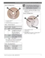
Figure 1:  PIR Detector 

1 – Detector base 

2 – Detector body 

3 – Tamper screw 

4 – Tamper switch 


2.


Push the tamper switch toward the tamper screw to 
unlock (

Figure 1

).  

3.


Hold the base and turn the detector body 
counterclockwise to remove from the base 
(

Figure 1

).  

4.


Position the base with the printed arrows pointing 
in the direction of the desired coverage and mount 
the base on the ceiling using the two mounting 
screws. Refer to 

Figure 2

 on page 3. 


1

2

3

4

Summary of Contents for ISN-CP1-CM-W50

Page 1: ...EN Installation Instructions PIR Detector ISN CP1 CM W50 ISN CP1 CM N100 ...

Page 2: ...por or high humidity that can cause condensation Mount the detector on 2 5 m 8 2 ft to 5 m 16 4 ft ceilings Install the detector so that intruders cross the coverage pattern Do not install the detector where pets are present Avoid installing the detector where cabinet doors curtains or other objects that can swing or move are within the coverage pattern 2 0 Installation Do not apply power until af...

Page 3: ...s 7 Spare No connection Refer to Table 2 to determine the minimum gauge wire required between the power source and the detector The table is based on one detector connected to a 12 VDC power source Table 2 Wiring Specifications Wire Gauge Maximum Length 0 3 mm2 AWG 22 700 m 2250 ft 0 5 mm 2 AWG 20 1200 m 3900 ft 0 75 mm2 AWG 18 1800 m 5900 ft When adding two or more detectors to a wire run the max...

Page 4: ... pyro sensor or the amplifier The Alarm output operates when this fault condition occurs 2 For UL Certificated installations you must set the sensitivity to 100 or 120 You must set the pulse count to 1 3 The detector activates an alarm when the count reaches the number of specified pulses within an interval of 10 sec or less The unit resets the count 10 sec after the last pulse As a guide set a pu...

Page 5: ...ft 46 ft 0 m 2 m 4 m 6 m 8 m 10 m 12 m 14 m 46 ft 39 5 ft 33 ft 26 5 ft 20 ft 13 ft 6 5 ft 0 ft 1 60 0 m 2 5 m 0 ft 8 ft 0 m 5 m 10 m 14 m 0 ft 33 ft 46 ft 2 16 5 ft 1 Top view 2 Side view Figure 6 ISN CP1 CM N100 Coverage Patterns 0 m 5 m 10 m 15 m 20 m 25 m 30 m 0 ft 16 5 ft 33 ft 49 ft 65 5 ft 82 ft 98 5 ft 0 m 2 8 m 0 ft 9 2 ft 1 0 m 5 m 10 m 15 m 20 m 25 m 30 m 0 ft 16 5 ft 33 ft 49 ft 65 5 f...

Page 6: ...magnetic noise or is wired too close to a power source Relocate the detector Reroute the wiring Sudden temperature fluctuation Exposed to direct sunlight Remove the heat source Readjust the coverage Block the light with blinds The detector body is not attached to the base Attach the detector body firmly on the base Alarm LED lights but there is no alarm output Controller not armed Arm the controll...

Page 7: ...rating Temperature and Humidity 20º C 4º F to 50º C 122º F 95 RH or less non condensing Alarm Contacts One selectable Form 1A NO or 1B NC semiconductor relay 0 1 A at 30 VDC Tamper Contacts One Form 1B NC 0 1 A at 30 VDC Alarm LED Indication Red Flashes when power is first applied and when the detector initiates self diagnosis Lights when the detector activates an alarm Mirror Angle Adjustment 30º...

Page 8: ... 2005 Bosch Security Systems 4998154997B Bosch Security Systems 130 Perinton Parkway Fairport NY 14450 9199 Customer Service 800 289 0096 Technical Support 888 886 6189 ...

Reviews: