


ISN-CP1-CM-W50, ISN-CP1-CM-N100
| Installation Instructions | 5.0 Troubleshooting Guide
6
Bosch Security Systems | 8/05 | 4998154997B
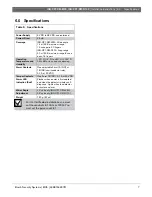
5.0 Troubleshooting Guide
Table 4: Detector Troubleshooting
Symptom Probable
Cause
Solution
No alarm or the Alarm LED never
lights
No power
Damaged wires
Improper connection
Insulation problem
Turn the power ON.
Change the wires.
Tighten the screws to improve the connection.
Object in the coverage pattern
Remove the object.
Adjust the coverage pattern.
Alarm LED does not light.
Turn DIP Switch 1-1 to ON.
The unit only detects occasionally
The intruder does not cross the
detector’s field of view.
Adjust the coverage pattern so that the
intruder crosses the field of view.
False alarms
The detector is installed too close to a
source of electromagnetic noise or is
wired too close to a power source.
Relocate the detector.
Reroute the wiring.
Sudden temperature fluctuation
Exposed to direct sunlight
Remove the heat source.
Readjust the coverage.
Block the light with blinds.
The detector body is not attached to
the base.
Attach the detector body firmly on the base.
Alarm LED lights but there is no
alarm output
Controller not armed
Arm the controller.
Tighten the screws to improve the connection.
Damaged wires
Improper connection
Insulation problem
Check with a tester.
Tighten the screws to improve the connection.
When Form 1B (NC) is used, the alarm
output is connected in parallel with the
outputs from other detectors.
Connect in series with the other detector’s
output.
Wire only one detector per loop.
Alarm LED flashes (one per
second).
The detector activates self diagnosis
due to mechanical failure.
Replace the detector.
Relays operate in reverse.
The relay setting is reversed.
Change the position of DIP Switch 1-2.


