36
| English
u
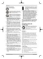
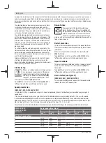
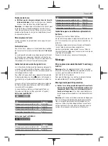
Always secure a grinding/cutting disc using only the
quick-clamping nut (21)
supplied
.
Press the spindle lock but-
ton
(3)
to lock the grinding
spindle. To tighten the
quick-clamping nut
(21)
,
fold up the bar and turn the
quick-clamping nut firmly
clockwise. Then fold down
the bar to secure the quick-
clamping nut.
It is not suf-
ficient to tighten the disc
along the edge.
Quick-clamping nuts
(21)
that are properly secured
and not damaged can be re-
moved by hand. To do this,
fold up the bar and turn the
quick-clamping nut firmly
anticlockwise. If the quick-
clamping nut is stuck, do
not attempt to loosen it with
a tool – always use a two-
pin spanner.
After fitting the mounting
flange and the grinding/cut-
ting disc, the free thread
length of the grinding
spindle must be
at least
4 mm
.
Ensure that the abrasive
tool is firmly seated, so that
it does not twist away from the spindle in the runout of the
power tool.
A plastic part (O-ring) is fitted around the cent-
ring collar in the mounting flange
(17)
.
If the
O-ring is missing or damaged,
the mounting
flange
(17)
must be replaced before operation
can resume.
u
After fitting the abrasive tool, check that the abrasive
tool is fitted correctly and can turn freely before
switching on the power tool. Make sure that the abras-
ive tool does not brush against the protective guard or
other parts.
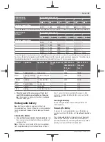
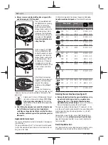
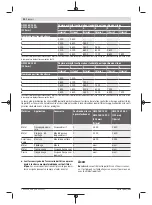
Approved abrasive tools
You can use all the abrasive tools mentioned in these operat-
ing instructions.
The permissible speed [min
-1
] or the circumferential speed
[m/s] of the abrasive tools used must at least match the val-
ues given in the table.
It is therefore important to observe the permissible
rota-
tional/circumferential speed
on the label of the abrasive
tool.
Max. [mm]
[mm]
[°]
D
b
s
d
α
[min
-1
] [m/s]
125
150
7.2
7.2
–
–
22.2
22.2
–
–
11,000
8500
80
80
125
150
4.2
4.2
–
–
22.2
22.2
–
–
11,000
8500
80
80
125
150
–
–
–
–
–
–
–
–
11,000
8500
80
80
75
30
–
M 14
–
11,000
80
125
125
150
150
24
19
24
19
–
–
–
–
M 14
22.2
M 14
22.2
–
–
–
–
11,000
11,000
8500
8500
80
80
80
80
125
–
–
M 14
–
11,000
80
83
–
–
M 14
–
11,000
80
α
s
125
150
6
6
10
10
22.2
22.2
> 0
> 0
11,000
8500
80
80
125
21
–
22.2
–
11,000
80
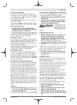
Rotating the machine head (see figure F)
u
Remove the battery from the power tool before carry-
ing out work on the power tool (e.g. maintenance,
changing tool, etc.). The battery should also be re-
moved for transport and storage.
There is risk of injury
from unintentionally pressing the on/off switch.
The machine head can be rotated in 90° increments. In this
way, the on/off switch can be brought into a more favourable
handling position for particular applications, e.g. for left-
handed tool users.
Completely unscrew the four screws (
➊
). Rotate the ma-
chine head carefully,
without removing it from the hous-
ing
, into the new position (
➋
). Screw in and retighten the
four screws (
➌
).
Dust/Chip Extraction
Dust from materials such as lead-containing coatings, some
wood types, minerals and metal can be harmful to one’s
1 609 92A 6WP | (08.06.2022)
Bosch Power Tools
Summary of Contents for GWS Professional 18V-15 C
Page 3: ... 3 A B C D 16 14 16 14 16 14 14 16 Bosch Power Tools 1 609 92A 6WP 08 06 2022 ...
Page 6: ...6 0 mm 4x 4x F 1 609 92A 6WP 08 06 2022 Bosch Power Tools ...
Page 552: ...552 standard Inox standard Metal 1 609 92A 6WP 08 06 2022 Bosch Power Tools ...
Page 556: ...556 1 609 92A 6WP 08 06 2022 Bosch Power Tools ...
Page 560: ...IV 1 609 92A 6WP 08 06 2022 Bosch Power Tools ...

