


Aspiration smoke detectors LSN improved
Installation | en
21
Bosch Sicherheitssysteme GmbH
Quick installation guide
2020.04 | 5 | F.01U.029.274
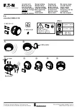
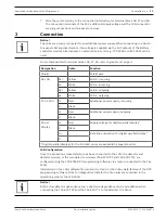
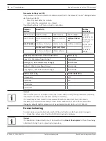
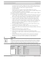
Setting the detector address
The Aspiration smoke detector address is set using the 8-pin DIP switches on the PC board
and a suitable sharp object. The default address is 0 (all DIP switches to off).
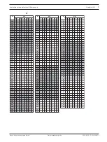
DIP switch settings for addresses 1 up to 127 are listed in graphic
06, page 5, for addresses
128 up to 254 in graphic
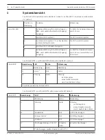
Address
(A)
Operating mode
Network structure
Loop
Stub
T-tap
0
Automatic address assignment in "improved
version" LSN mode
X
X
-
1 to 254
Manual address assignment in improved version
LSN mode
X
X
X
255 = CL Automatic address assignment in classic LSN
mode (address range: max. 127)
X
X
-
x = possible, - = not possible
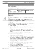
Notice!
It is not permitted to use different operating modes in one loop/stub/T-tap next to each
other.
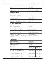
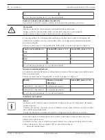
Setting the Fan Voltage
For FAS-420 systems, the standard fan voltage setting is 6.9 V.
To switch to 9 V, pull out jumper BR4.
For motherboard with jumper BR4, refer to graphic
04, page 4.
Fan voltage
Jumper BR4, pin no. 1+2
6.9 V
X
9 V
O
X = pin pair bypassed, O = pin pair open
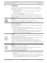
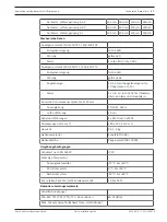
Setting the Fan Voltage (SL Variant)
For FAS-420 systems, the standard fan voltage setting is 6.9 V.
!
Caution!
For SL variants, always remove jumper BR4 from the motherboard.
Close or open jumper the jumpers BR1 and BR2 only when the device is switched off.
Re-initialize the airflow if you have switched the fan voltage.
The fan voltage on the fan activation circuit board on SL devices is set using the jumpers BR1
and BR2. The default setting is marked in bold.
For motherboard with jumpers BR1, BR2 and BR4, refer to graphic
04, page 4.
Fan voltage with FC‑2
Jumper BR1, pin no. 1+2
Jumper BR2, pin no. 1+2
6.5 V
O
X
6.9 V
X
O
9 V
O
O