background image

22 EP Series

Subject to change without prior notice                                      Revised 12-13

8733922168

Maintenance

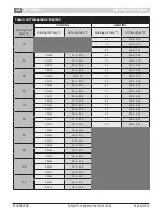
Table 1: 

Dimensions

Model

Vertical 

Unit 

(In)

Horizontal 

Unit 

(In)

Supply Air

Connection 

(In)

Return Air

Connection* 

 (In)

Replacement Fil-

ter Nominal Size* 

(In)

Width

Depth

Height

Width

Depth

Height

Width

Height

Width

Height


EP007

21.75

21.75

32.75

21.75

43.25

16.75 11.75

7.75

H: 20.25 

V: 18.0

H: 13.0 

V: 13.0

H: 15"x20"x1" (1) 

V: 15"x20"x1" (1)

EP009

21.75

21.75

32.75

21.75

43.25

16.75 11.75

7.75

H: 20.25 

V: 18.0

H: 13.0

V: 13.0

H: 15"x20”x1” (1) 

V: 15"x20”x1” (1)

EP012

21.75

21.75

32.75

22.25

45.25

19.75

7.75

11.75 H: 20.25 

V: 18.0

H: 16.0

V: 16.0

H: 18"x20”x1” (1) 

V: 18”x20”x1” (1)

EP015

21.75

21.75

39.25

22.25

45.25

19.75 13.75

13.75 H: 20.25 

V: 18.0

H: 16.0 

V: 18.0

H: 18"x20”x1” (1) 

V: 20"x20”x1” (1)

EP018

21.75

21.75

39.25

22.25

45.25

19.75 13.75

13.75 H: 20.25 

V: 18.0

H: 16.0 

V: 18.0

H: 18"x20"x1" (1) 

V: 20"x20"x1" (1)

EP024

21.75

26.25

47.25

26.25

54.75

22.00 13.75

15.75 H: 30.25 

V: 22.0

H: 18.0 

V: 22.0

H: 20”x30”x1” (1)
V: 24"x24"x1” (1)

EP030

24.25

33.50

47.25

30.25

68.25

22.00 15.75

15.75

H: 35.0 

V: 28.0

H: 18.0 

V: 22.0

H: 20”x34.5”x1" (1) 

V: 24"x30"x1" (1)

EP036

24.25

33.50

47.25

30.25

68.25

22.00 15.75

15.75

H: 35.0 

V: 28.0

H: 18.0 

V: 22.0

H: 20"x34.5"x1" (1) 

V: 24"x30"x1" (1)

EP042

26.25

33.50

58.25

30.25

79.00

22.00 17.75

17.75 H: 48.25 

V: 28.0

H: 18.0 

V: 30.0

H: 24"x20"x1" (2) 

V: 16"x30"x1" (2)

EP048

26.25

33.50

58.25

30.25

79.00

22.00 17.75

17.75 H: 48.25 

V: 28.0

H: 18.0 

V: 30.0

H: 24"x20"x1" (2) 

V: 16"x30"x1" (2)

EP060

26.25

33.50

66.25

30.25

89.25

22.00 17.75

17.75 H: 56.25 

V: 28.0

H: 18.0 

V: 38.0

H: 28"x20"x1" (2) 

V: 20"x30"x1" (2)

EP070

26.00

33.50

66.50

30.00

89.00

22.00 17.75

17.75 H: 56.25 

V: 28.0

H: 18.0 

V: 38.0

H: 28"x20"x1" (2) 

V: 20"x30"x1" (2)

*H = Horizontal Unit; V = Vertical Unit

Summary of Contents for EP015

Page 1: ...EP Series Installation and Maintenance Manual 8733922168 Revised 12 13 ...

Page 2: ...c All rights reserved TABLE OF CONTENTS Model Nomenclature 2 Initial Inspection 3 General Description 3 Moving and Storage 3 Safety Considerations 3 Location 3 Installation 4 Mounting Vertical Units 4 Mounting Horizontal Units 4 Condensate Drain 5 Duct System 5 Electrical 6 Thermostat Connections 7 Safety Devices and the UPM Controller 7 Sequence Of Operation 11 Unit Options Hot Gas Reheat 11 Elec...

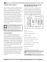
Page 3: ... is not needed for immediate installation upon its arrival at the job site it should be left in its shipping carton and stored in a clean dry area Units must only be stored or moved in the normal upright position as indicated by the UP arrows on each carton at all times If unit stacking is required stack units as follows Vertical units less than 6 tons no more than two high horizontal units less t...

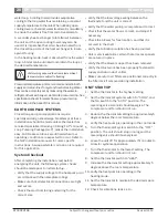
Page 4: ...enough to hold their weight they are typically suspended above a ceiling by threaded rods The rods are usually attached to the unit corners by hanger bracket kits P N 930 008 See Figure 2 The rods must be securely anchored to the ceiling Refer to the hanging bracket assembly and installation instructions for details Horizontal units installed above the ceiling must conform to all local codes An au...

Page 5: ... Heat pump condensate trapping This connection must be in conformance with local plumbing codes A trap must be installed in the condensate line to insure free condensate flow Heat Pumps are not internally trapped A vertical air vent is sometimes required to avoid air pockets See Figure 3 The length of the trap depends on the amount of positive or negative pressure on the drain pan A second trap mu...

Page 6: ... due to electrical shock ELECTRICAL Caution Always disconnect power to the unit before servicing to prevent injury or death due to electrical shock or contact with moving parts All field wiring must comply with local and national fire safety and electrical codes Power to the unit must be within the operating voltage range indicated on the unit s nameplate On three phase units phases must be balanc...

Page 7: ...iagnostic Connection 9 24VAC Power Input 10 Compressor Contact Output 11 High Pressure Switch Connection 12 Call for Compressor Y1 13 Low Pressure Switch Connection 14 24VAC Power Common 15 Condensate Overflow Sensor 16 Dry Contact 17 UPM Ground Standoff Caution If the thermostat is provided with a malfunction light powered off of the common C side of the transformer a jumper between R and COM ter...

Page 8: ...e leaving water temperature and protect your heat pump from freezing if a freeze sensor is included Evaporator freeze protection sensor mounted between the thermal expansion device and the evaporator monitors refrigerant temperature between the evaporator coil and thermal expansion valve If temperature drops below or remains at freeze limit trip for 30 seconds the controller will shut down the com...

Page 9: ...s during troubleshooting or verification of unit operation Note that operation of the unit while in test mode can lead to accelerated wear and premature failure of the unit The TEST switch must be set back to NO for normal operation FREEZE SENSOR The default setting for the freeze limit trip is 30 F sensor number 1 however this can be changed to 15 F by cutting the R30 resistor located on top of t...

Page 10: ...Reset Y Alarm PULSE Test NO Dry Contact Normally Open NO Considerations 1 Always check incoming line voltage power supply and secondary control voltage for adequacy Transformer primaries are dual tapped for 208 and 230 volts Connect the appropriate tap to ensure a minimum of 18 volts secondary control voltage 24 volts is ideal for best operation 2 Long length thermostat and control wiring leads ma...

Page 11: ...et point temperature and the humidity is above set point the unit will operate in the hot gas reheat mode first by cooling and dehumidifying then reheating the air using hot refrigerant gas before delivering it to the space usually 2 F to 5 F below room temperature The unit is operating as a dehumidifier By reheating the air along a constant sensible heat line the relative humidity of the supply a...

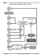
Page 12: ...C HPC 1 LPC 1 FRZ TEMP LIM CON 0 INITIAL POWER UP T ASC OR RS SEC TIME 30 SEC TIME 120 SEC COUNT 2 Start Timer Start Timer CC Output On CC Output Off Blink Code On Status LED Report Alarm Fault Hard Lockout ALR Output On Pulse Blink Code On Status LED Soft Lockout Record Alarm Start Counter If Applicable Start Anti Short Cycle Start Random Start Up Lockout Can Be Set To 4 Via Dip Switch Power Swit...

Page 13: ...e Special Considerations Some applications require special consideration to maximize the performance of the hot gas reheat function Low Temperature Well Water Indoor Pool Dehumidifying During Winter Months Consult the factory for special application considerations Refrigerant Flow Path Ahotgasreheatvalveandareheatcoilareincludedinthe refrigerantcircuit Therefrigerantcircuitinthecooling andheatingm...

Page 14: ...andle the structural loss load on A protective coating is highly recommended for all pool applications due to the highly corrosive chemical environment Operating Pressures and Temperatures Operating pressures and temperatures in the reheat mode vary slightly from standard cooling mode operating characteristics The variations are as follows Discharge Pressure 5 to 20 PSIG Discharge Gas Temperature ...

Page 15: ...ir e In situations of low fluid temperature the amount of hot gas could be limited and the design leaving air temperature may not be attained This can be remedied by the use of field supplied head pressure controlled water regulating valves or manually adjusting the water flow rates accordingly Depending on the application in the unoccupied mode the unit should be disabled through some type of rel...

Page 16: ...ng loads for example a conference center Without a hot gas bypass circuit the evaporating temperature will fall and ice could form on the coil restricting air flow and aggravating the situation Eventually the coil could be totally blocked resulting in possible refrigerant liquid entering the compressor and failure of the system The hot gas bypass valve is located in the discharge line from the com...

Page 17: ...meet application requirements and to ease troubleshooting Only one switch can be enabled at a time Refer to table for airflow settings CFM Selector FIg 9 Item 2 must remain with only A being enabled ADJUST Selector can be adjusted to NOM or TEST NOM and can be adjusted as needed by application TEST is used for troubleshooting to override unit airflow to 100 Caution Do not set theADJ DIPswitch to t...

Page 18: ...heets for the water flow and pressure drop information in the back of this manual The discharge water from the heat pump is not contaminated in any manner and can be disposed of in various ways depending on local codes i e discharge well dry well storm sewer drain field stream pond etc When using a single water well to supply both domestic water and the heat pump care must be taken to insure that ...

Page 19: ...isolation and unit water flow balancing No unit should be connected to the supply or return piping until the water system has been completely cleaned and flushed to remove any dirt piping chips or other foreign material Supply and return hoses should be connected together during this process to ensure the entire system is properly flushed After the cleaning and flushing has taken place the unit ma...

Page 20: ...tc water loop A cooling tower provides evaporative cooling to the loop water thus maintaining a constant supply temperature to the unit When utilizing open cooling towers chemical water treatment is mandatory to ensure the water is free from corrosive elements A secondary heat exchanger plate frame between the unit and the open cooling tower may also be used It is imperative that all air be elimin...

Page 21: ...nt the equipment is used in In a single family home that is not under construction changing or cleaning the filter every 60 days may be sufficient In other applications such as motels where daily vacuuming produces a large amount of lint filter changes may be need to be as frequent as biweekly See unit specifications for replacement filter sizes Note that horizontal units containing two filters ar...

Page 22: ... x20 x1 1 EP018 21 75 21 75 39 25 22 25 45 25 19 75 13 75 13 75 H 20 25 V 18 0 H 16 0 V 18 0 H 18 x20 x1 1 V 20 x20 x1 1 EP024 21 75 26 25 47 25 26 25 54 75 22 00 13 75 15 75 H 30 25 V 22 0 H 18 0 V 22 0 H 20 x30 x1 1 V 24 x24 x1 1 EP030 24 25 33 50 47 25 30 25 68 25 22 00 15 75 15 75 H 35 0 V 28 0 H 18 0 V 22 0 H 20 x34 5 x1 1 V 24 x30 x1 1 EP036 24 25 33 50 47 25 30 25 68 25 22 00 15 75 15 75 H ...

Page 23: ...al lbs Shipping Weight Vertical Horizontal lbs EP007 36 0 15 140 165 160 185 EP009 36 0 15 154 172 174 192 EP012 36 0 31 166 173 186 205 EP015 36 0 31 191 190 208 218 EP018 36 0 31 195 198 212 222 EP024 36 0 48 229 307 242 340 EP030 36 0 39 269 358 292 404 EP036 36 0 62 281 369 304 415 EP042 36 0 62 334 400 360 465 EP048 36 0 62 340 405 366 470 EP060 36 0 62 396 452 422 520 EP070 36 0 85 444 494 4...

Page 24: ... 25 2 50 75 63 20 5 25 8 60 23 3 32 8 80 67 21 5 27 70 22 0 31 0 85 71 22 3 28 1 80 20 5 29 0 60 75 63 19 2 24 7 60 26 5 37 1 80 67 20 1 25 8 70 25 1 35 1 85 71 20 9 26 8 80 23 4 32 7 70 75 63 17 9 23 8 60 29 8 41 4 80 67 18 7 24 9 70 28 2 39 1 85 71 19 5 25 8 80 26 3 36 4 80 75 63 16 6 23 0 60 32 7 45 7 80 67 17 4 24 0 70 30 9 43 1 85 71 18 1 25 0 80 28 8 40 2 85 75 63 16 0 22 6 80 67 16 8 23 6 8...

Page 25: ... 161 240 267 129 158 282 343 136 167 297 362 10 119 153 238 265 122 158 246 273 125 161 251 279 124 150 274 333 131 159 289 351 15 119 153 246 273 122 158 254 281 125 161 259 287 117 146 262 320 123 154 276 337 80 5 121 155 265 294 124 160 273 303 127 163 279 309 148 184 299 366 156 194 315 387 10 121 155 276 306 124 160 285 316 127 163 291 322 143 176 286 352 151 185 302 371 15 121 155 285 315 12...

Page 26: ... 5 8 2 51 10 5 6 2 43 3 25 9 3 4 03 12 5 8 4 3 64 4 13 5 5 85 15 11 8 5 11 012 2 1 7 0 72 042 7 3 0 1 30 3 3 4 1 50 8 75 4 4 1 91 4 5 8 2 51 10 5 6 1 2 66 5 5 10 2 4 45 13 25 9 3 4 04 7 15 8 6 88 16 13 2 5 74 015 2 1 6 0 69 048 8 3 8 1 65 3 3 3 1 44 10 67 6 3 2 73 4 5 5 2 41 12 7 8 3 38 5 5 9 8 4 28 14 10 3 4 46 7 15 2 6 60 16 13 2 5 75 018 3 4 1 1 80 060 9 4 7 2 04 4 7 0 3 02 12 7 8 3 38 5 10 4 4...

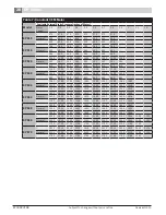
Page 27: ...00 670 640 585 530 EP030 High 1225 1195 1170 1140 1110 1075 1010 940 745 Medium 1110 1075 1045 1015 985 955 915 880 700 Low 955 925 890 860 825 790 750 715 685 EP036 High 1440 1420 1400 1380 1345 1315 1240 1165 1005 845 Medium 1340 1315 1290 1270 1245 1225 1180 1135 990 845 Low 1190 1165 1140 1115 1090 1065 1040 1020 915 810 EP042 High 1645 1635 1610 1585 1560 1535 1510 1485 1460 1430 Medium 1455 ...

Page 28: ...0 850 850 850 850 850 EP036 1380 1380 1380 1380 1380 1380 1380 1380 1380 1380 Normal 1200 1200 1200 1200 1200 1200 1200 1200 1200 1200 1020 1020 1020 1020 1020 1020 1020 1020 1020 1020 EP042 1610 1610 1610 1610 1610 1610 1610 1610 1610 1610 Normal 1400 1400 1400 1400 1400 1400 1400 1400 1400 1400 1190 1190 1190 1190 1190 1190 1190 1190 1190 1190 EP048 1840 1840 1840 1840 1840 1840 1840 1840 1840 1...

Page 29: ...29 EP Series 8733922168 Revised 12 13 Subject to change without prior notice TYPICAL WIRING DIAGRAMS PSC Motor Hot Gas Reheat Single Phase Single Stage ...

Page 30: ...30 EP Series Subject to change without prior notice Revised 12 13 8733922168 Typical Wiring Diagrams X13 Motor Single Phase Single Stage ...

Page 31: ...31 EP Series 8733922168 Revised 12 13 Subject to change without prior notice Typical Wiring Diagrams EON Motor Economizer Three Phase Single Stage ...

Page 32: ...32 EP Series Subject to change without prior notice Revised 12 13 8733922168 Unit Check Out Sheet X13 Motor Dual Power Supply Three Phase Single Stage ...

Page 33: ...33 EP Series 8733922168 Revised 12 13 Subject to change without prior notice Electric Heat Wiring Diagram ...

Page 34: ...34 EP Series Subject to change without prior notice Revised 12 13 8733922168 Electric Heat Wiring Diagram ...

Page 35: ..._____ Fluid Flow gpm ______________________________ ______________________________ Compressor Volts Amps ______________ ______________ ______________ ______________ Blower Motor Volts Amps ______________ ______________ ______________ ______________ Source Fluid Type _______________________________ ______________________________ Fluid Flow gpm ______________________________ ________________________...

Page 36: ...e compressor Compressor motor grounded Internal winding grounded to the compressor shell Replace compressor Compressor windings Open After compressor has cooled check continuity of the compressor windings If the windings are open replace the compressor Unit off on high pressure control Discharge pressure too high In COOLING mode Lack of or inadequate water flow Entering water temperature is too wa...

Page 37: ...ersing valve creating bypass of refrigerant from discharge of suction side of compressor Replace reversing valve Operating pressures Compare unit operation pressures to the pressure temperature chart for the unit TXV Check TXV for possible restriction or defect Replace if necessary Moisture noncondensables The refrigerant system may be contaminated with moisture or noncondensables Reclaim refriger...

Page 38: ...38 EP Series Subject to change without prior notice Revised 12 13 8733922168 ...

Page 39: ...39 EP Series 8733922168 Revised 12 13 Subject to change without prior notice ...

Page 40: ...601 N W 65th Court Ft Lauderdale FL 33309 Phone 866 642 3198 Fax 954 776 5529 www boschtaxcredit com www fhp mfg com Revised 12 13 ...

Reviews: