13
EP Series
8733922168
Revised 12-13 Subject to change without prior notice
Hot Gas Reheat
Sequence of Operation - On/Off Control
The sequence of operation in the cooling and
heating mode is the same as a regular heat pump.
In the reheat mode on a call from the humidistat the
reheat relay coil is energized through the “H” circuit.
The blower relay, reversing valve and compressor
contactor are energized through the contacts of the
reheat relay. See typical wiring diagrams at the end
of the manual. The cooling relay remains de-
energized enabling the reheat solenoid (Note: The
reheat mode always operates in the cooling mode.)
Should the temperature in the space increase above
set point the compressor terminal Y is energized
which will de-energize the reheat valve putting the
unit into the straight cooling mode. A call for cooling
or heating will always take precedence over hot gas
reheat.
Hot Gas Reheat Controllers
There are several ways to control heat pumps with
hot gas reheat. You should choose the means that
best suits your specific application. See typical
wiring diagrams and the end of the manual for
some possible control sequences. Most heat pump
compatible thermostats in conjunction with a
humidistat are acceptable for use, (Note: “O”
output for reversing valve energized in cooling
mode is required.) Combination thermostats/
humidistat are also available.
Special Considerations
Some applications require special consideration to
maximize the performance of the hot gas reheat
function:
• Low Temperature Well Water
• Indoor Pool Dehumidifying During Winter Months
Consult the factory for special application
considerations.
Refrigerant Flow Path
A hot gas reheat valve and a reheat coil are included in the
refrigerant circuit. The refrigerant circuit in the cooling
and heating mode is identical to a standard heat pump.
In the reheat mode the compressor discharge gas is
diverted through the reheat valve to the reheat coil
which is located downstream of the cooling coil. The
superheated refrigerant gas reheats the air leaving the
cooling coil. The hot refrigerant gas then passes
though the water to refrigerant coil where it is
condensed to a liquid. From this point the rest of the
cooling cycle is completed as in a regular heat pump.
There are two check valves to prevent refrigerant flow
into the reheat coil during standard cooling/heating
cycles. A small copper bleeder line is connected to the
outlet line of the reheat coil and between the
expansion valve outlet and distributor to the air coil.
This line is necessary to let any liquid/oil that may have
migrated to the reheat coil during reheat to escape
during standard cooling/heating modes. (See Figure 5)
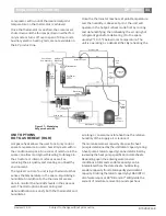
Figure #8 – Modulating Hot Gas Reheat Valve
Handle, set screw
& flow indicator
at 0 VDC position
Self Adapt–OFF
CW Rotation
Direct Acting Feedback
Rotate CW
Rotate CW
Scale Position Indicator on Handle
Drive Pin Location
To Reheat Coil
To Condenser/
Reversing Valve
Weld
From Compressor


