background image

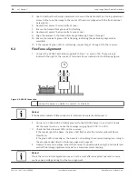
11. At the end of the setup, the receiver’s green LED flashes and the voltage decreases to a

range from 3.8 VDC to 4.2 VDC. Use this voltage as a reference when you compare later
readings to determine the need for cleaning. If the voltage is not within this range, press
the Setup button.

12. After setup, remove the test cable.
13. Reconnect the D306 or D307 connector if used.
14. Replace and secure the access door.
 

Troubleshooting

Transmitter

LED

Condition

Solution

Flashing

Normal


Off

1. There is no power at the transmitter.
2. The Aim Mode button not pressed.
3. The transmitter is faulty.

1. Restore power to Terminals 1 and 2.
2. Press the Aim Mode button.
3. Replace the transmitter.

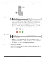
Receiver - Aim Mode (cover off)

Red
LED

Yellow
LED

Green
LED

Terminals
4 and 5

Terminals
6 and 7

Condition

Solution

On

On

Flashing Open

Open

The alignment is
acceptable.


On

On

On

Open

Open

The beam is
blocked or the
receiver is
misaligned.

Clear the beam
path or realign
the receiver.

On

Flashing Flashing Open

Open

The sensitivity
setting is invalid.

Set the receiver
to the proper
setting.

On

Off

Off

Open

Open

There is no power.

Check for
power at
Terminals 8 and
9.


7

7.1

7.2

22

en | Notices

Long-range Beam Smoke Detectors

2014.01 | 06 | F.01U.068.899

Installation Instructions

Bosch Security Systems, Inc.

Summary of Contents for D296 Series

Page 1: ...Long range Beam Smoke Detectors D296 D297 en Installation Instructions ...

Page 2: ......

Page 3: ...start installation flowchart 13 5 Wiring 14 5 1 Wiring a single detector 14 5 2 Wiring a remote indicator 15 5 3 Wiring multiple detectors 16 6 Setup 17 6 1 Preliminary alignment 18 6 2 Fine Tune alignment 20 7 Troubleshooting 22 7 1 Transmitter 22 7 2 Receiver Aim Mode cover off 22 7 3 Receiver Normal Mode cover on 23 8 Maintenance and Testing 24 8 1 Fire alarm reset 24 8 2 Reference voltage adju...

Page 4: ...determined by turning the equipment off and on correct the interference by Reorienting or relocating the receiving antenna Increasing the separation between the equipment and the receiver Connecting the equipment to an outlet on a circuit different from the circuit to which receiver is connected Consulting the dealer or an experienced radio or TV technician for help Codes and standards Install tes...

Page 5: ...oke obscures the beam the receiver senses a decrease in the signal strength and measures that decrease The receiver compares the signal level with two preset thresholds an alarm threshold that is set using the sensitivity switch and a trouble threshold that is preset at approximately 10 If the signal falls below the alarm threshold for the programmed alarm period the receiver signals an alarm see ...

Page 6: ...eceiver Clear the beam path of moving objects Avoid areas with normal smoke concentrations such as kitchens and garages Do not install detectors where the normal ambient temperatures are below 22 F 30 C or above 130 F 54 C Set sensitivity based on the distance between the transmitter and receiver For information on selecting and setting sensitivity see Design for the expected fire load page 8 and ...

Page 7: ... path Use correct wire gauge and length Beam smoke detectors are often used to protect large areas requiring long wire runs to power the detectors and signal alarm conditions The voltage available at the end of long wire runs might not be sufficient to power the detector especially when the system is running on backup battery power Use the correct wire gauge when installing detectors For the prope...

Page 8: ...r to a square or octagonal electrical mounting box of 4 in 10 cm can bow the mounting plate Bowing can occur because the mounting box screw tabs are below flush with the top edges of the mounting box Over tightening the mounting screws bows the mounting plate inward at the bottom causing the optics to aim low Irregularities in the flatness of the mounting box edge surfaces or at the screw tabs wor...

Page 9: ...eceiver Determine the total obscuration needed for an alarm and select the sensitivity setting needed according to the following table Total Obscuration at Alarm Sensitivity Switch Setting 20 2 30 0 or 3 40 4 50 5 60 1 or 6 70 7 Long range Beam Smoke Detectors Notices en 9 Bosch Security Systems Inc Installation Instructions 2014 01 06 F 01U 068 899 ...

Page 10: ...ngs 0 or 1 for a 5 sec response time For instructions on setting the sensitivity see Sensitivity setting page 11 Mounting Notice Use this product in indoor dry applications only 1 Install a 4 in square or octagonal electrical box or equivalent to a rigid surface that is not subject to movement or vibrations 2 Remove the screw on the receiver s access door Then remove the cover s four screws indica...

Page 11: ... based on the distance between the transmitter and receiver For a list of distances including some settings that overlap see the following table Select a lower setting for a more sensitive detection or select a higher setting for better immunity to false alarms Switch Setting Sensitivity Alarm Response Beam Length 0 30 5 sec 30 ft to 100 ft 9 m to 31 m 1 60 5 sec 100 ft to 350 ft 31 m to 107 m 2 2...

Page 12: ...ch to your selected setting The sensitivity switch is located to the right of the optical module The indicator or pointer marking runs along the side of the switches shaft as indicated in the following figure Figure 4 3 Sensitivity Switch 12 en Notices Long range Beam Smoke Detectors 2014 01 06 F 01U 068 899 Installation Instructions Bosch Security Systems Inc ...

Page 13: ...Quick start installation flowchart Figure 4 4 Installation Flowchart 4 2 Long range Beam Smoke Detectors Notices en 13 Bosch Security Systems Inc Installation Instructions 2014 01 06 F 01U 068 899 ...

Page 14: ...ble Figure 5 1 Wiring a single detector 1 Fire alarm control panel FACP 3 End of line EOL resistor 2 Receiver 4 Transmitter Type Terminal Description Transmitter terminals 1 and 2 Input power terminals for operating voltages see Specifications page 26 Receiver terminals 1 2 and 3 Form C auxiliary relay contacts On fire alarm Terminals 1 and 2 open Terminals 2 and 3 close short 5 5 1 14 en Notices ...

Page 15: ...o reset install a switch in series with Terminal 8 Wiring a remote indicator A D306 Remote Indicator Plate is shipped with the D296 as a standard accessory The D306 has three LEDs to indicate the detector s condition and status and test points for measuring the sensitivity voltage Although the D306 is not required the manufacturer recommends its installation to check the detector s condition from ...

Page 16: ...tiple detectors For smooth flat ceilings mount the detectors so there is spacing of no more than 60 ft 18 3 m between beam paths with no more than half of this spacing between the beam path and side wall the wall parallel to the beam path Other spacings depend on ceiling height air flow characteristics and response requirements The minimum spacing between alternated adjacent detectors is 1 10th th...

Page 17: ...itter and receiver are not alternated ensure the spacing between the detectors is 1 5th the distance from the transmitter to the receiver Setup Before performing a setup ensure all connections are made and secure Then apply power to the transmitter and receiver 1 To allow the transmitter to power up while the cover is off press the transmitter s Aim Mode button located above the green LED as indic...

Page 18: ...the green LED either flashing or steadily on If all LEDs are off check for power and proper polarity on Terminals 8 and 9 Figure 6 2 Receiver LEDs 1 Alarm LED red 3 Normal LED green 2 Trouble LED yellow 4 Depending on your application an aid to alignment might be necessary If so mount an aiming light D309 or equivalent as close to the receiver as possible preferably on top of the receiver 5 Point ...

Page 19: ...t image or receiver s image if aiming light is not used in the mirror The optical module points at objects seen in the mirror when the front bore sight is in the center of the rear bore sights as indicated in the following figure Figure 6 4 Alignment Mirror 1 Rear bore sights 2 2 Front bore sight 4 If the optical module is initially aimed too high or too low adjust the Vertical Fine Tuning adjustm...

Page 20: ...ection 1 Connector wires a white b red c black Notice If the Remote Indicator Plate connector is installed temporarily disconnect it 2 Connect a 20 000 Ω VDC VOM or greater to the D1005 s black and red leads Set the meter scale so you see the readings ranging from 0 VDC to 5 VDC 3 Check the three receiver LEDs on the receiver If the receiver gets the beam the green LED flashes and the red and yell...

Page 21: ...l this cable to P6 Route the test cable through the opening in the cover white lead towards center of the receiver 9 At this point you can perform an Alarm Test Connect the D1005 s white and black wires Reset the receiver by temporarily removing power 10 Press the receiver s Setup button located below the P6 and test cable connection as indicated in the following figure Figure 6 6 Receiver Setup B...

Page 22: ... button not pressed 3 The transmitter is faulty 1 Restore power to Terminals 1 and 2 2 Press the Aim Mode button 3 Replace the transmitter Receiver Aim Mode cover off Red LED Yellow LED Green LED Terminals 4 and 5 Terminals 6 and 7 Condition Solution On On Flashing Open Open The alignment is acceptable On On On Open Open The beam is blocked or the receiver is misaligned Clear the beam path or real...

Page 23: ...en Trouble If the reference voltage is less than 2 VDC dust on the lens reduced the signal strength or vibration misaligned the receiver Clean the transmitter and receiver covers If the reference voltage does not return to 3 8 VDC to 4 2 VDC realign the receiver and press the Setup switch Off On Flashing Open Open If the reference voltage is greater than 4 2 VDC the beam strength increased because...

Page 24: ...ted to the detector remove the receiver access door and measure the reference voltage using the supplied test cable For cable connection see Fine Tune alignment page 20 If the voltage is less than 3 8 VDC or greater than 4 2 VDC remove the access cover and press the setup button to initiate a reset of the reference voltage The reset can take 1 min to 2 min Cleaning Clean the outside of the covers ...

Page 25: ... check the sensitivity level of the detector As the signal level decreases because of dust or dirt buildup on the lenses or system misalignment the voltage reading also decreases Field sensitivity measurements Notice Testing these detectors activates a fire alarm Inform all concerned personnel before performing a test The detectors automatically compensate for the effects of dust and dirt accumula...

Page 26: ...ontacts Normally Open N O contacts rated 1 A 60 VDC maximum for DC resistive loads do not use with capacitive or inductive loads Auxiliary alarm contacts Normally Open N O contacts rated 1 A 60 VDC maximum for DC resistive loads do not use with capacitive or inductive loads Trouble contacts Normally Closed N C contacts rated 1 A 60 VDC maximum for DC resistive loads do not use with capacitive or i...

Page 27: ...do not use with systems incorporating an alarm verification feature Signal Delay Fire Selectable 30 sec or 5 sec Trouble 20 2 sec Spacing distance between systems 60 ft 18 m maximum spacing confirmed by Underwriters Laboratories UL testing Transmission range 30 ft 9 m to 350 ft 107 m Tamper Receiver Access door tamper switch in series with trouble contacts Transmitter When the cover is removed the...

Page 28: ...Bosch Security Systems Inc 130 Perinton Parkway Fairport NY 14450 USA www boschsecurity com Bosch Security Systems Inc 2014 F 01U 068 899 ...

Reviews: