


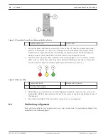


Figure 6.1: Transmitter Circuit Board Showing Aim Mode Button
1 Aim Mode button
2 Green LED
2.
Ensure the green LED flashes on and off. If this LED is off, check for power and proper
polarity on Terminals 1 (–) and 2 (+). If the green LED is steadily lit, you have a faulty
transmitter. To begin the process of obtaining a replacement, call the Bosch National
Repair Center at (800) 366-2283 or send an e-mail to [email protected].
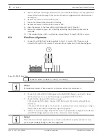
3.
Check the three receiver LEDs indicated in the following figure. It is normal for all three
LEDs to be on at this time, with the green LED either flashing or steadily on. If all LEDs
are off, check for power and proper polarity on Terminals 8 (–) and 9 (+).
Figure 6.2: Receiver LEDs
1 Alarm LED (red)
3 Normal LED (green)
2 Trouble LED (yellow)
4.
Depending on your application, an aid to alignment might be necessary. If so, mount an
aiming light, D309 or equivalent, as close to the receiver as possible, preferably on top of
the receiver.
5.
Point the aiming light at the transmitter using it as your aiming guide.
Preliminary alignment
Each optical module has two alignment mirrors, one on each side, for preliminary alignment as
indicated in the following figure.
6.1
18
en | Notices
Long-range Beam Smoke Detectors
2014.01 | 06 | F.01U.068.899
Installation Instructions
Bosch Security Systems, Inc.


