background image

D278S/D298S 

|


Installation Guide | 4.0 

Base POPIT Addresses 


Bosch Security Systems, Inc. | 11/10 | F01U069160-11 

5


4.0  Base POPIT Addresses 

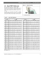
Each D278S and D298S has a specific address 
determined by setting the seven DIP switches located 
on the detector’s base. Refer to Figure 4. The base’s 
address does not depend on the base’s location in the 
circuit. 
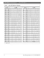
Use Table 3 to set the address for the D9112 or D9124 
FACP. If adding the base to a previous version FACP, 
set Switch 0 to ON and set all other switches to OFF. 
 

Figure 4: 

Address Switches 

1

Z

-

Z

+

1


1 -  Address switches 


Table 3: 

Base POPIT Addresses  


Point Bus 

Switch


 Point 

Bus 

Switch


A


A


45 

009 129 


037 157 


010 

130 


038 

158 


011 131 


039 159 


012 

132 


040 

160 


013 133 


041 161 


014 

134 


042 

162 


015 135 


043 163 


016 

136 


044 

164 


017 137 


045 165 


018 

138 


046 

166 


019 139 


047 167 


020 

140 


048 

168 


021 141 


049 169 


022 

142 


050 

170 


023 143 


051 171 


024 

144 


052 

172 


025 145 


053 173 


026 

146 


054 

174 


027 147 


055 175 


028 

148 


056 

176 


029 149 


057 177 


030 

150 


058 

178 


031 151 


059 179 


032 

152 


060 

180 


033 153 


061 181 


034 

154 


062 

182 


035 155 


063 183 


036 

156 


064 

184 


Bullet (

) = ON 


Summary of Contents for D278S

Page 1: ...EN Installation Guide Addressable Smoke Detector Base D278S D298S ...

Page 2: ...n cause the detector to fail to indicate an alarm Bosch is not responsible for improperly installed tested or maintained detectors 1 Select a suitable mounting location according to the instructions in the Smoke Detectors Technical Service Note P N 31347 2 Route all system wiring to the D278S or D298S location 3 Mount the D278S or D298S refer to Item 1 in Figure 1 using the two oblong mounting hol...

Page 3: ...cuit 22 AWG 0 8 mm 20 AWG 1 0 mm 18 AWG 1 2 mm 16 AWG 1 5 mm 1 to 70 1822 ft 555 m 2898 ft 883 m 4608 ft 1405 m 7327 ft 2233 m 71 to 80 1594 ft 486 m 2536 ft 773 m 4032 ft 1229 m 6411 ft 1954 m 81 to 90 1417 ft 432 m 2254 ft 687 m 3584 ft 1092 m 5699 ft 1737 m 91 to 100 1275 ft 389 m 2028 ft 618 m 3225 ft 983 m 5129 ft 1563 m 101 to 110 1159 ft 353 m 1844 ft 562 m 2932 ft 894 m 4663 ft 1421 m 111 ...

Page 4: ...2 to wire the PAM 4 Auxiliary Relay Module Figure 3 D298S and PAM 4 Wiring 1 D298S 2 Red wire 3 Black wire 4 Relay contact wiring 5 PAM 4 Auxiliary Relay Module Table 2 PAM 4 Relay Module Contact Wiring Wire Lead Color Description Red Positive Black Negative Yellow Normally closed Blue Common Orange Normally closed Contact descriptions are inactive not energized ...

Page 5: ...ch 0 to ON and set all other switches to OFF Figure 4 Address Switches 1 Z Z 1 1 Address switches Table 3 Base POPIT Addresses Point Bus Switch Point Bus Switch A B 0 1 2 3 4 5 6 A B 0 1 2 3 45 5 6 009 129 037 157 010 130 038 158 011 131 039 159 012 132 040 160 013 133 041 161 014 134 042 162 015 135 043 163 016 136 044 164 017 137 045 165 018 138 046 166 019 139 047 167 020 140 048 168 021 141 04...

Page 6: ...00 220 069 189 101 221 070 190 102 222 071 191 103 223 072 192 104 224 073 193 015 225 074 194 106 226 075 195 107 227 076 196 108 228 077 197 109 229 078 198 110 230 079 199 111 231 080 200 112 232 081 201 113 233 082 202 114 234 083 203 115 235 084 204 116 236 085 205 117 237 086 206 118 238 087 207 119 239 088 208 120 240 089 209 121 241 090 210 122 242 091 211 123 243 092 212 124 244 093 213 1...

Page 7: ...ications D278S Addressable Smoke Detector Base with Head D298S Addressable Smoke Detector Base with Head D298S Addressable Smoke Detector Base with PAM 4 Relay Module and Head Auxiliary Power Voltage Range 9 6 VDC to 13 9 VDC 18 9 VDC to 28 0 VDC 18 9 VDC to 28 0 VDC Idle Current 2 5 mA 2 0 mA 2 0 mA Alarm Current 40 mA 18 mA 34 mA ...

Page 8: ...Bosch Security Systems Inc 130 Perinton Parkway Fairport NY 14450 USA www boschsecurity com Bosch Security Systems Inc 2010 ...

Reviews: