background image

CCS 900 Ultro

 Built-in MP3 recorder (CCS-CURD only) | en

27

Bosch Security Systems B.V.

Installation and Operating Manual

IOM_CCS900 | V1.0 | 2010.06

7.3.2

Deleting files

Use this option to delete files.

1.

Press the up or down button to select the file to delete. The filename will change on the 

display as the button is pressed.

2.

Press the delete file button to delete the selected file.

3.

Press the confirm delete button to confirm the file to delete permanently or cancel the 

delete command of the selected file by pressing the button “cancel delete”.

4.

Press the select button to select the next value to change (see following section).

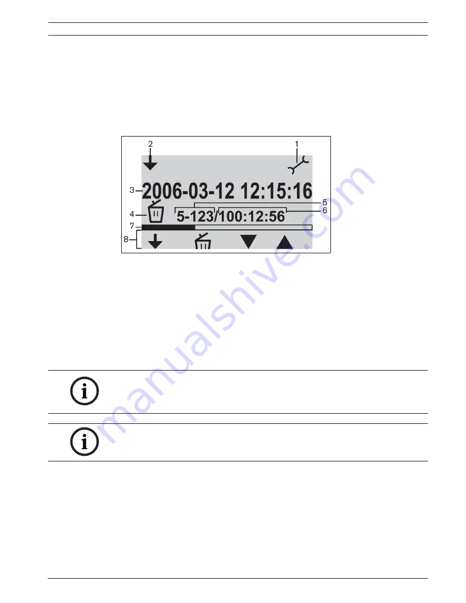
Figure 7.3

Delete screen

1.

Mode selected icon: Set-up mode is selected.

2.

Change mode icon: Shows the user when another mode can be selected.

3.

File name: Shows the name of the selected audio file (default name is the date and time 

of the recording).

4.

Set-up item: Shows the selected set-up item.

5.

File counter: Shows the selected file number and the total number of files.

6.

Time counter: Shows the elapsed time of all recordings on disk.

7.

Space usage and separator line: Shows the used capacity of all files and the free space 

on the SD card or internal memory.

8.

Button icons: See table 7.2.

NOTICE! 

With refer to the file counter in figure 7.3. If the total number of files exceeds 99 then the last 

digit or two digits might not be displayed.Example: if file 86 from all 120 files is selected it will 

be shown as 86-12.

NOTICE! 

After deleting a file, the software jumps back to the delete file screen.

Summary of Contents for CCS 900 Ultro

Page 1: ...CCS 900 Ultro Discussion System en Installation and Operating Manual ...

Page 2: ......

Page 3: ... 5 10 Mains connection 14 5 11 Connecting a USB cable 15 6 Operation 16 6 1 Testing the connection of the Delegate and Chairman Units 16 6 2 Using the microphone button of the Delegate Unit 16 6 3 Possible To Speak 17 6 4 Using the microphone button of the Chairman Unit 17 6 5 Using the priority button 18 6 6 Priority mode settings in Chairman Unit 18 6 7 Open mode 19 6 8 Open mode with auto switc...

Page 4: ...back icons 32 7 5 2 Pre listening to and playing back files 33 8 Troubleshooting 34 9 Technical data 36 9 1 System Electrical and Electro Acoustical Characteristics 36 9 1 1 The Control Unit CU 36 9 1 2 Combined Units 38 9 2 Mechanical Data 38 9 2 1 Control and Power Supply Unit 38 9 2 2 Delegate Chairman Units 38 9 3 General data 39 9 3 1 System Environmental Conditions 39 9 3 2 Equipment Range 4...

Page 5: ...formation required to install and operate the CCS 900 Ultro Discussion System Conventions WARNING Warnings draw attention to instructions that must be followed to prevent personal injury CAUTION Cautions draw attention to instructions that must be followed to prevent damage to the equipment NOTICE Notes draw attention to special instruction tips or other useful information ...

Page 6: ...wer for the CU itself Chairman Unit s and Delegate Unit s With the use of Digital Acoustic Feedback Suppression the loudspeaker volume can be increased significantly before feedback appears A Digital Acoustic Feedback Suppressor is only available in CCS CUD CCS CURD A Delegate Unit enables participants to actively join in a discussion i e speaking and listening by means of a microphone controlled ...

Page 7: ...te microphone can be activated If a new delegate presses his microphone button the microphone unit of the current speaker will be switched off Chaiman only mode Only the Chairman Units can be activated Test mode For proper installation check All the red LED s and the light rings of the connected units will lit if properly connected 4 Speaker volume control of all connected Delegate and Chairman Un...

Page 8: ...te chairman loudspeakers 13 Digital Acoustic Feedback Suppressor DAFS switch to activate or deactivate the DAFS optional 14 USB connector Used for downloading recorded speech to a PC optional 15 Mains input connection Use the included mains cord to connect the CU to the mains socket In some countries it may be necessary to replace the supplied mains cable by a local one Brown live blue neutral and...

Page 9: ...tically muted when the microphone is on 4 Bi color LED indicator above the microphone push button Red for microphone on white for Possible To Speak indication Delegate Unit only 5 7 pole circular female socket for loop through connection to the next unit 6 2m flying lead connection cable with sturdy moulded 7 pole circular male connector for connection to the previous unit or CU 7 Rotary volume co...

Page 10: ...nect the Delegate 2 and Chairman 3 Units to the trunk connectors of the CU 1 Use an extension cable 4 if necessary 5 2 Connecting up to 150 units The CCS 900 Ultro can be used with up to 150 units by adding a maximum of 2 additional Control Units acting as power supply units only Please contact your local Bosch representative for the installation instructions Figure 5 2 Connecting 6 x 25 units ...

Page 11: ...ng clamps can be used in combination with the extension cables to prevent accidental disconnection 5 4 Connecting an external microphone Figure 5 4 Put the external microphone 2 connector in the microphone input of the CU 1 Adjust the sensitivity by use of the gain control 3 Use only microphones with balanced output The microphone input provides a 12V phantom power supply ...

Page 12: ... the external microphone input is possible with the included 50dB attenuator This way of connection allows interruption of the wireless microphone by the chairman s priority button 5 6 Recording playback the conversation Figure 5 6 Connect the cabling of the recorder device 2 to the recorder input and output of the CU 1 Use the gain control 3 to adjust the sensitivity of the recorder input of the ...

Page 13: ...r 2 to the telephone input and output of the CU 1 The telephone coupler is further connected to the telephone wall socket 4 and a telephone 3 for dialing A connection to a telephone network must always be made via a telephone coupler that provides adequate isolation between the telephone network PBX and the CCS 900 Ultro system The telephone coupler shall also meet all relevant requirements for th...

Page 14: ...ust be in position 1 loop through if the insertion input output is not used 5 10 Mains connection Figure 5 10 Use the supplied mains cord set 5 to connect the CU 1 to a protective earthed mains socket 2 Press the on off switch 3 to power up the system the display 4 will be lit CCS CURD only WARNING The CU must be earthed via the mains supply for safety reasons and to ensure the specified audio per...

Page 15: ...SB cable to connect the CU 1 to a PC Data can then be downloaded from the CU to the PC CCS CURD only See section 7 for more information CAUTION Do not connect the USB cable and audio output input to the same PC otherwise the system will not work CAUTION Do not disconnect the USB cable or shut down the Control Unit without following the PC disconnection procedures ...

Page 16: ... the mode selector in the test position all light ring indicators and red LEDs of the Delegate and Chairman Units must lit if properly connected 6 2 Using the microphone button of the Delegate Unit Figure 6 2 Depending on the position of the microphone mode switch on the CU pressing the microphone button on a Delegate Unit will activate the delegate microphone Pressing again switches the microphon...

Page 17: ...e color of the LED will change to red If the maximum number of active microphones in the system is reached the LED will be off and the microphone can not be switched on The Possible To Speak indication can be disabled 0 indication disabled 1 indication enabled default 6 4 Using the microphone button of the Chairman Unit Figure 6 4 Pressing the microphone button on a Chairman Unit always activates ...

Page 18: ...tes the chairman microphone Figure 6 5 2 Release of the priority button Figure 6 5 3 will either leave the Delegate Units deactivated or activates them again depending on priority mode settings 6 6 Priority mode settings in Chairman Unit Figure 6 6 Remove the cable relief bracket 1 to set the chime and microphone switches in the required position at priority 0 no chime at priority 1 default chime ...

Page 19: ... be active at the same time 6 8 Open mode with auto switch off Figure 6 8 Select the max number 1 2 3 or 4 of delegate microphones which can be activated by the delegates themselves at the same time If the speaker is silent for approximately 30 seconds the active microphone switches off automatically NOTICE Chairmen can always switch on and off their microphones and are not included in the maximum...

Page 20: ... time a delegate presses the microphone button on a Delegate Unit it will override the currently active Delegate Unit So only one delegate microphone is active at the same time chairman microphones can always be switched on 6 10 Chairman only mode Figure 6 10 Only the Chairman Units B can be activated Delegates A can not switch on their microphones ...

Page 21: ... and adjust the loudspeakers for maximum level without feedback Switch Digital Acoustic Feedback Suppression on by changing the switch 1 to position 1 Then set the loudspeaker volume to the required level but increasing the volume level more than 2 or 3 steps is not recommended NOTICE With the use of Digital Acoustic Feedback Suppression the loudspeaker volume can be increased significantly before...

Page 22: ...st the volume using the monitoring volume control The maximum level is controlled by the setting of the volume control for Delegate and Chairman Units 6 14 Using a headphone Figure 6 14 Use the rotary volume control 1 to adjust the volume of the headphones connected to the left and or right side of the units Inserting a headphone jack mutes the loudspeaker The maximum level depends on the setting ...

Page 23: ...ecorded files have a maximum duration of 60 minutes After 60 minutes the file will be automatically closed and a new file will be created This process is repeated as long as recording is active or until the SD card is full Recorded speech is saved on an SD card which is inserted into the top of the unit see following figure or saved internally After recording the SD card can be removed or the reco...

Page 24: ...ft button 2 3 Soft button 3 4 Soft button 4 5 Soft Button 5 6 User display displays user data and icons see section 7 2 3 7 Slot for SD card Slot for inserting the SD card 8 LED for SD card LED is on during recording 7 2 2 Modes of operation Refer to Figure 7 1 Use button 1 to select the mode of operation An icon appears in the top right hand corner of the display to show which mode is selected Th...

Page 25: ...e and playback mode shows how much of the file has been played 6 Icons The space underneath the Progress and separator line is reserved for icons Various icons are used during recording pre listening and playback The icons vary according to the mode selected for more information see section 7 3 through section 7 5 7 Time Shows the time in hours minutes and seconds 8 Time counter Shows the elapsed ...

Page 26: ...creen is selected Time Indicates that the time set up screen is selected Bit rate Indicates that the bit rate set up screen is selected Microphone recording Unit will only record if one or more delegate microphones pick up a signal or if a signal is present on a external input Continuous recording Unit will continuous record Confirm delete Confirms file to be deleted Delete file Permanently delete...

Page 27: ...de selected icon Set up mode is selected 2 Change mode icon Shows the user when another mode can be selected 3 File name Shows the name of the selected audio file default name is the date and time of the recording 4 Set up item Shows the selected set up item 5 File counter Shows the selected file number and the total number of files 6 Time counter Shows the elapsed time of all recordings on disk 7...

Page 28: ...r and then press the next button 3 to select the next value to change 4 Set the date year month and day as described in the previous step and then press the select button 2 to jump to the time set up screen 5 Set the time hours minutes and seconds using the same method as described in step 3 and then press the select button to jump to the bit rate set up screen see following section 7 3 4 Selectin...

Page 29: ...ion 7 3 6 Set internal external recording options Refer to figure 7 1 1 Press the down button to switch between record to the SD card or record to the internal memory refer to table 7 2 2 Press the change mode button 1 to exit the set up mode NOTICE If more than 50 Delegate Units are connected by using additional Control Units the option record when one or more microphones are active may not work ...

Page 30: ...ivate recording Stop Stops recording session New file Creates a new file during recording recording continues but the data is saved under a new file name The time counter on the display is also reset Change card Allows the user to change the SD card during recording see section 7 4 3 Change card timer Graphically shows the user how many seconds are remaining before the new card must be inserted Ho...

Page 31: ...ecording will stop The last minute of recorded discussion will also be lost When there is 5 minutes of recording time left on the card three short beeps will be played through the monitor loudspeaker This is to warn the operator to change the card If the card is not changed within 5 minutes a long beep will be played through the monitor loudspeaker at 0 minutes and the card exchange function will ...

Page 32: ...is shown at the top right hand corner of the display Start Starts the pre listen or playback session depending on mode selected The first file in the list will be played As soon as this file has been played the next valid file will start Pause Pauses the pre listen or playback session depending on the mode selected When pre listen or playback has been paused the start icon will appear and start to...

Page 33: ...p right hand corner of the display depending on the mode selected 2 Press the start button 2 to pre listen to or playback files The MP3 tag is shown on the display If there is no MP3 tag the filename is shown instead 3 During pre listening or playback you can switch between pre listen and playback by pressing the change mode button 1 press the pause button to temporarily halt playback press the st...

Page 34: ... Increase the distance between headphone and microphone or disconnect headphones when not in use If available switch on Digital Acoustic Feedback Suppression Part of system not working Interrupted trunk line cabling Check the trunk line cabling connections between the units and the CU also use the test function on the CU No sound via delegate chairman loudspeakers Insertion switch in wrong positio...

Page 35: ... almost full Remove old files recordings Format the SD card The SD card is too slow Use a faster SD card Recorded files missing on SD card The SD card was removed during recording Always stop recording before removing SD card Select SD card exchange before removing SD card User display is blank During CU power up the USB cable was connected to the CU and PC while the PC was switched off Make sure ...

Page 36: ...ompatible high speed cards are advised Line telephone coupler and insertion in outputs unbalanced Input sensitivity 14 dBV 11dBV nominal maximum Input impedance 33 kOhm Output level 14 dBV 11dBV nominal maximum Output impedance 500 Ohm Recorder in output unbalanced mono Input sensitivity 20 dBV 5 dBV nominal maximum Input sensitivity adjustment 0 20 dB Input impedance 47 kOhm for L and R channel O...

Page 37: ...Number of Open Microphones NOM 1 dB Auto microphone switch off function selectable on the Control and Power Supply Unit After approximately 30 sec not speaking sound level below 64 dB SPL the microphone is automatically switched off System limits Number of Delegate Chairman Units connected to CU Maximum in total 50 Maximum per trunk output 25 Maximum trunk length using CCS 900 Ultro standard cabli...

Page 38: ...Mounting free standing on a table top or mounted in a 19 rack requires 3HU Height Units with bracket set LBB 3311 00 Information about how to make the necessary brackets for table flush mounting is included Dimensions HxWxD 84 x 361 x 143 mm with 5 5 mm feet 3 4 x 14 2 x 5 6 in with 0 22 in feet Weight CCS CU version 1 6 kg 3 5 lb CCS CUD version 1 7 kg 3 7 lb CCS CURD version 1 8 kg 4 0 lb Dimens...

Page 39: ...1 to 113 F Ambient humidity Operational 20 95 RH Storage and transport 0 99 RH Air pressure 600 mBar 1100 mBar Safety according to EN 60065 and according to UL 60065 Resistance to shock vibration bump and transport according to IEC 60068 5G acceleration EMC emission according to EN 55103 1 and FCC rules part 15 class A EMC immunity according to EN 55103 2 EMC approvals affixed with the CE mark Mai...

Page 40: ...lly according to the illustrations in chapter 10 2 Delegate Unit s CCS DS short microphone CCS DL long microphone Chairman Unit s CCS CMS short microphone CCS CML long microphone Installation cable with connectors LBB 3316 00 100 m Extension cables LBB 3316 05 5m LBB 3316 10 10m Cable locking clamps LBB 4117 00 set of 25 pieces Cable clamp DCN DISCLM set of 25 pieces Transport suitcase for 10 Dele...

Page 41: ...line 2 GND 3 Audio distribution line 4 Control line 1 5 Control line 2 6 V supply 7 V supply 10 1 2 External Microphone XLR B 1 GND 0V phantom supply 2 Signal 12V phantom supply 3 Signal 12V phantom supply Phantom supply according to DIN45596 10 1 3 CINCH Connector C 1 Signal 2 Screen 10 1 4 Mains Connector D 1 Mains 2 Earth 3 Mains 10 1 5 Headphone Jack plug 3 5mm E 1 Tip Signal 2 Ring Signal 3 S...

Page 42: ...CCS900 V1 0 2010 06 Installation and Operating Manual Bosch Security Systems B V 10 1 6 Schematics of connectors LBB 3316 00 Figure 10 2 Connector pin connections Pin number Color 1 White 2 Shield 3 Violet 4 Yellow 5 Green 6 Red 7 Blue ...

Page 43: ...ufficient space for cable connections Mounted into a table using the flush mount bracket On a table Therefore drill four holes in the table and fasten the CU with four M3 screws B The Delegate and Chairman Units can only be attached on a table Therefore drill two holes in the table and fasten the unit with two self tapping M3 screws A Figure 10 3 Mounting into a table Figure 10 4 Mounting on a tab...

Page 44: ...CCS900 V1 0 2010 06 Installation and Operating Manual Bosch Security Systems B V 10 3 Bracket for Flush Mounting The drawing below gives the necessary information how to make a bracket for flush mounting the CU into a table Figure 10 5 ...

Page 45: ......

Page 46: ...Bosch Security Systems B V Kapittelweg 10 4800 RA Breda The Netherlands www boschsecurity com Bosch Security Systems B V 2010 ...

Reviews: