


Control Operations Guide Bosch Buderus SSB800SA | SSB1000SA | SSB1000TL Boilers
| 5
Bosch Thermotechnology Corp. | 01.2020
Data subject to change
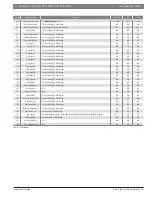
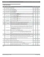
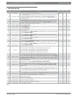
2 Boiler Parameters
Number
Parameter Name
Description
Default
Min
Max
1
CH Mode
Set Central Heating
CH Mode
based upon the desired control strategy for the boiler.
0
0
4
3
CH Set Point
Central Heating Setpoint only applies to
CH Mode
#0 ( On/Off using dry contacts) and
CH Mode
#3 (Permanent set point
demand). The value set for
CH Setpoint
will be the boiler supply water temperature (system supply for cascade).
140 °F
86 °F
194 °F
109
Calc. SetP. Offset
Factor used in the PID calculation to offset
CH Setpoint
up or down.
0 °F
-1.8 °F
1.8 °F
110
CH Min Setpoint
CH Mode
4 setpoint at 1.5 - 2 VDC.
68 °F
68 °F
122 °F
111
CH Max Setpoint
CH Mode
4 setpoint at 9-10 VDC.
194 °F
122 °F
194 °F
5
Boiler Pump Overrun
The post circulation time of the module pump at the end of the heating request. The amount of time in seconds the boiler
pump contacts will be energized after the demand for heat has ended.
30 sec.
0 sec. 900 sec.
7
CH Hysteresis Up
If the supply temperature reaches a temperature above the
CH Setpoint
plus
CH Hysteresis up
, then the burner will be
switched OFF.
36 °F
0 °F
36 °F
112
CH Hysteresis Down
If the supply temperature reaches a temperature below the
CH Setpoint
minus
CH Hysteresis down
, then the burner will
be switched ON.
9 °F
0 °F
36 °F
9
Anti-Cycle Period
The amount of time in seconds the boiler will wait before restarting in 10 second increments.
180 sec. 10 sec. 900 sec.
10
Anti-Cycle Temp. Period Diff
In addition to the
Anti Cycle Period
(see above) the boiler will monitor the System Supply Temperature Sensor. If the
system temperature drops below the
Anti Cycle Temp. Period Diff
, the
Anti Cycle Period
will be ignored and burner will
start.
28.8 °F
0 °F
36 °F
14
Max Power CH
The Maximum burner power for Central Heating can be limited during operation.
100%
50%
100%
15
Min Power CH
The Minimum burner power for Central Heating operation can be limited during operation.
1%
1%
30%
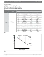
19
Design Supply Temp
The water temperature the boiler will supply at
Design Outdoor Temperature
.
194 °F
86 °F
194 °F
20
Design Outdoor Temp
The outdoor air temperature at which the boiler will supply the
Design Supply Water Temperature
.
23 °F
-13 °F
77 °F
21
Baseline Supply Temp
The water temperature the boiler will supply at the
Baseline Outdoor Temperature
.
104°F
68°F
194°F
22
Baseline Outdoor Temp
The outdoor air temperature at which the boiler will target the
Baseline Supply Temperature
.
68°F
32°F
86°F
23
Design Supply Min Limit
The minimum supply water temperature the heating system will provide to the system.
86°F
39.2°F 179.6°F
24
Design Supply Max Limit
The maximum supply water temperature the heating system will provide to the system.
194°F
80.6°F
194°F
25
Warm Weather Shut Dn
The temperature above which heating is no longer necessary. All calls for heat will be ignored as long as the outdoor
temperature remains above the
Warm Weather Shutdown
value.
71.6°F
32°F
95°F
26
Boost Temp Increment
Boost Temp Increment
is active for
CH Mode
1. If a call for heat has not been satis
fi
ed within the period of time de
fi
ned
within
Boost Time Delay
(see below) the targeted supply temperature will be increased by the value of
Boost Temp
Increment
. This process of Boosting supply water will continue until the call for heat is satisi
fi
ed.
0°F
0°F
54°F
27
Boost Time Delay
Boost Time Delay
is active only for
CH Mode
1. If a call for heat has not been satis
fi
ed within the time limit (in minutes)
de
fi
ned within
Boost Time Delay
, the supply water temperature will be increased by
Boost Temp Increment
(see above).
Supply water temperature increases again if the call for heat still is not satis
fi
ed in another time increment.
20 min.
1 min. 120 min.
28
Night Setback Temp
Only available for
CH Modes
#2 and #3. The value the heating curve will be reset as long as contacts #11 & #12 are "open"
(i.e. via an external clock timer or switch).
18°F
0°F
90°F
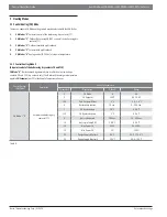
35
DHW Mode
When an Indirect tank is present in the system set
DHW Mode
to
1
when using the factory supplied 10K ohm sensor or set
to
2
if using a third-party aquastat. Default value is
0
(Off).
0
0
2
113
Max Power DHW
The maximum power for DHW can be limited during operation.
50%
50%
100%
114
Min Power DHW
The minimum power for DHW operation can be limited during operation.
1%
1%
30%
36
DHW Tank Hyst. Down
The necessary temperature drop of the indirect tank temperature needed before the boiler will begin to recover the tank.
Only active when
DHW Mode
(par. #35) is set to
1
and a 10k ohm sensor is used.
9 °F
0 °F
36 °F
37
DHW Tank Hyst. Up
The necessary temperature drop of the indirect tank temperature needed before the boiler will begin to recover the tank.
Only active when
DHW Mode
(par. #35) is set to
1
and a 10k ohm sensor is used.
9 °F
0 °F%
36 °F
38
DHW Tank Supply Extra
The Target Supply Water temperature to the indirect coil is equal to
DHW Tank Setpoint
(par. #48) plus
DHW Tank Supply
Extra
.
27 °F
0 °F
54 °F
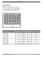
42
DHW Priority
Default setting is
Time
Time - DHW has priority to CH during
DHW Max Priority Time
*
Off - CH always has priority to DHW
On - DHW always has priority to CH
Parallel - DHW always has priority to CH. CH pump can be started if CH has a request and
CH setpoint
> supply for DHW
TIME
N/A
N/A
Table 1


