


Installation of accessories
19
AWE – 6721835317 (2021/09)
7. Open the fill valve VW2 and admit water into the pipe leading to the
heat pump.
8. Continue filling until only water emerges from the hose at the drain
and the outdoor unit no longer contains air bubbles.
9. Close the drain valve VA0 and continue filling the system until the
reading at the pressure gauge GC1 is 2 bar.
10.Close the fill valve VW2.
11.Connect the power supply to the heat pump and indoor unit.
12.Remove the hose from the drain valve VC0.
13.Clean the particle filter SC1.
14.Close the valves VC3 and SC1 to the heating system.
15.Check the pressure after a while and add more via the fill valve VW2
if the pressure is below the required pressure.
9
Installation of accessories
9.1
EMS-BUS for accessories
The following applies to accessories that are connected to the EMS-BUS
(see also the installation instructions for the respective accessories):
▶ If several BUS units are installed, there must be a minimum spacing of
100 mm between them.
▶ If several BUS units are installed, connect them in series or in a star
configuration.
▶ Use cable with a minimum cross-section of 0.5 mm
2
.
▶ In case of external inductive interferences (e.g. from PV systems),
use screened cables. Only earth the shielding to the casing on one
side.
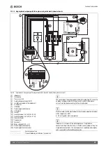
▶ Connect the cable on the installation module to terminal EMS-BUS.
If a component is already connected to the EMS terminal, establish the
connection in parallel to the same terminal according to fig. 17.
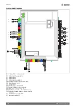
Fig. 17 EMS connection on the installer module
9.2
External connections
Max. load at the relay outputs: 2 A, cos
If the load is higher, it is
necessary to install an intermediate relay.
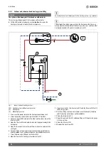
• Output VC0 switches when changing over between heating and DHW
mode and is used if a buffer storage tank is installed.
• Relay output PK2 is active in cooling mode. Possible application
areas:
– Changing between cooling/heating for fan convectors. The
control device of the fan convector must feature the relevant
function.
– Pump control in a separate circuit which is exclusively intended
for cooling mode.
– Control of underfloor heating circuits in damp areas.
– If the setting "Switch off PC1 in DHW mode" has been set to "No",
PK2 also switches when defrosting. This function serves as a
backdraught shutter for fan convectors.
9.3
Maximum sensor
In some countries a high limit safety cut-out is required in underfloor
heating circuits. The high limit safety cut-out is connected to the
installation module at the external input 1–3 (
Fig. 34). Adjusting the
function for the external input (
instructions for control device).
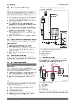
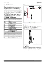
9.4
Installation of the domestic hot water cylinder
If the domestic hot water cylinder is installed lower than the heat pump
(e.g. in the cellar), a natural circulation can occur that leads to heat loss
in the cylinder.
▶ Install a non-return valve in the circuit to prevent natural circulation if
the installation height of the domestic hot water cylinder is below the
heat pump.
Fig. 18 Hot water cylinder
[1]
Non-return component
The connection instructions are in the cylinder documentation.
EMS NSC/IP
0010012105-002
CW1
TW1
1