background image

Installation

13

AWE – 6721835317 (2021/09)

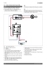
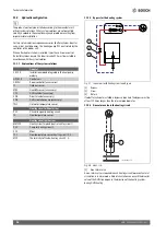
Standard: Electrical connection for integrated auxiliary heater 
(factory configuration)

Fig. 11 Electrical standard connection for the integrated electric 

booster heater

[1]

400 V (three-phase current) mains voltage for indoor unit

[2]

230 V (alternating current) mains voltage for heat pump 
(alternating current)

[3]

230 V ~1 N mains voltage for accessories

Table 7 Power steps of the electric booster heater

K3 is blocked during compressor mode. When only the electric booster 
heater is running and the compressor is switched off, the following 
power steps apply: 3/6/9 kW.

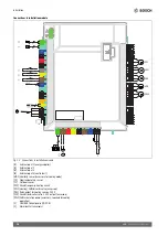
Alternative version, alternating current, see arrangement of 
jumpers

The heat pump has a separate power supply and is connected via the 
building connection.

Fig. 12 Alternative version

[1]

230 V 1 N~, mains voltage

[2]

230 V 1 N~, EMS accessory

Capacity

K1

K2

K3

2000

W

X

4000

W

X

6000

W

X

X

9000

W

X

X

X

3

2

1

1

2

0010025729-001

Summary of Contents for AWE

Page 1: ...6721835317 2021 09 GB Installation Manual Indoor unit for air to water heat pump AWE AWE 5 9 13 17 ...

Page 2: ...um sensor 19 9 4 Installation of the domestic hot water cylinder 19 9 5 DHW cylinder temperature sensor TW1 20 9 6 Diverter valve VW1 20 9 7 Domestichotwatercylinder solarthermalheating 20 9 8 Room controller Bosch CR10H only 21 9 9 Several heating circuits with heating circuit module 21 9 10 Circulation pump for DHW PW2 21 9 11 Installation with swimming pool 21 9 12 Buffer VC0 bypass valve 21 9 ...

Page 3: ...ll not be assumed for any resulting damage H Installation commissioning and service The product may only be installed brought into operation and maintained by trained personnel Use only original spare parts H Handover to the user When handing over instruct the user how to operate the heating system and inform the user about its operating conditions Explainhowtooperatetheheatingsystemanddraw the us...

Page 4: ... Follow the guidance of BS7593 for treatment of water in domestic hot water heating systems1 Do not use anti freeze glycol products Suitable water treatment products inhibitors cleaners can be obtained from the following manufacturers Table 3 If the limits for water hardness stated in table 2 are exceeded the performance of the heat pump will deteriorate over time If this performance degradation c...

Page 5: ... units AWE are intended for assembly in a house and for connection to Compress 7001i AW Compress 7400i AW heat pumps installed outdoors Possible combinations Table 5 Possible combinations 3 3 Declaration of conformity Thedesignandoperatingcharacteristicsofthisproductcomplywiththe European and national requirements The CE marking declares that the product complies with all the applicable EU legisla...

Page 6: ...er medium 4 Electrical heater 5 Automatic air vent valve VL1 6 Cable feed for power input 7 Cable feed for sensor CAN BUS and EMS BUS 8 Heat transfer medium inlet primary from the heat pump 9 Heat transfer medium outlet primary to the heat pump 10 Flow to heating system 11 Pressure gauge 12 Overpressure discharge from the pressure relief valve 13 Return from the heating system 3 6 Product dimensio...

Page 7: ...ndavoidauxiliaryheateroperation the following configuration is recommended 30 m2 floor area for heat pump 5 9 100 m2 floor area for heat pump 13 17 System with radiators without mixer and buffer cylinder If the system only contains a few radiators the auxiliary heater may be activated in the final phase of the defrosting process The radiator thermostats must be opened fully 1 radiator with 500 W r...

Page 8: ...stall the particle filter according to the system solution 4 Connect the indoor unit to the heating system 5 Install the outdoor temperature sensor and if necessary the room temperature dependent controller 6 Connect CAN BUS cable to heat pump and indoor unit 7 Install any accessories solar module pool module etc 8 If required connect EMS BUS cable to accessories 9 If present fill and vent the DHW...

Page 9: ...t for safe and efficient DHW mode All heat conducting pipework must be provided with suitable thermal insulation according to applicable regulations Incoolingmode allconnectionsandlinesmustbeinsulatedaccordingto applicable standards to prevent condensation Route a leakage water hose downwards to a frost free drain Sizepipeworkasspecifiedintheinstallationinstructionsfortheheat pump Connect the pipi...

Page 10: ...se the heating system valves particle filter SC1 and VC3 3 Connect a hose to VA0 and route the other end to a drain Open the drain valve VA0 4 Open the fill valve VW2 and admit water into the pipes leading to the heat pump 5 Open the manual air vent until water flows without air and close the vent again 6 Continue filling until only water comes out of the hose by the drain and the outdoor unit s c...

Page 11: ... the corresponding markings on the modules Accessoriessuchasoutputlimiterstobe connectedtothe CAN BUS are connected inparallelontheinstallationmodulecardintheindoorunit to the CAN BUS connection for the heat pump Accessories can also be connected in series with other units connected to the CAN BUS The heat pump and indoor unit are connected to each other by a communication line the CAN BUS A LIYCY...

Page 12: ...trol device Connect cable as shown in the wiring diagram Reattach the cover of the control device and the front plate of the indoor unit Fig 10 Cable feeds 1 Cable feed for sensor CAN BUS and EMS BUS 2 Cable feed for electrical connection Considerations for three phase and single phase connections NOTICE Risk of product malfunction The fuse size should be appropriate to the selected setting for po...

Page 13: ...s voltage for accessories Table 7 Power steps of the electric booster heater K3 is blocked during compressor mode When only the electric booster heater is running and the compressor is switched off the following power steps apply 3 6 9 kW Alternative version alternating current see arrangement of jumpers The heat pump has a separate power supply and is connected via the building connection Fig 12 ...

Page 14: ...rol unit MD1 Humidity sensor accessory for cooling mode T0 Flow temperature sensor T1 Outdoor sensor PC1 Circulation pump heating circuit VW1 Heating DHW diverter valve accessory PK2 Relay output for cooling season 230 V VC0 Circulation diverter valve 230 V output accessory PW2 DHW circulation pump accessory required for cooling operation 1 CAN BUS to heat pump I O PCB 2 Alarm buzzer accessory 2 P...

Page 15: ...ternative for EMS bus A Star configuration and connectioninseries with external junction box B Star configuration C Serial connection 1 Installation circuit board 2 Accessory modules room temperature dependent controller heating circuit module and solar module B C A 1 1 1 2 2 2 2 2 2 2 2 2 2 2 2 ...

Page 16: ...it with an integrated electric booster heater and heating system Z1 Heating system without mixer 1 Heat pump 2 Manual air vent valve 1 Connect the power supply of the outdoor and indoor unit 2 Activateonlytheelectricboosterheaterandmakesurethatthepump PC1 is running 3 Pull PWM contact PC0 off the pump PC0 so that it runs at maximum speed 4 Only deactivate the auxiliary heater when the pressure has...

Page 17: ...ime when the operating pressure is too low it can be damaged Eliminate any leaks in the system that are indicated when the pressure switch is triggered The triggering of the pressure switch only blocks the electric booster heater The heating pump PC0 and the heat pump can continue to run if there is a risk of frost Pressure switch Theindoorunithasapressureswitchwhichtriggersoncethepressurein the h...

Page 18: ...ticles and contamination from entering the heat pump Over time the filter can become blocked and must be cleaned Tocleanthefilter thesystemdoesnotneedtobeemptied Thefilterand shut off valve are integrated Cleaning the strainer Close the valve 1 Unscrew the cap manually 2 Take out the strainer and clean it by running water over it or by pressure cleaning Reinstall the strainer For proper assembly m...

Page 19: ...he same terminal according to fig 17 Fig 17 EMS connection on the installer module 9 2 External connections Max load at the relay outputs 2 A cos If the load is higher it is necessary to install an intermediate relay OutputVC0 switches whenchanging over between heatingandDHW mode and is used if a buffer storage tank is installed Relay output PK2 is active in cooling mode Possible application areas...

Page 20: ...g 20 Contact closed connection A open Duringdomestichotwaterheating thecontactisclosedandconnection A is open Fig 21 Contact open connection B open In heating mode the contact is opened and connection B is open Ifthe3 waydivertervalvehasaMolexplug only terminals 2 3 and6 are assigned Make the following connections on the installation module N Connection to terminal N VW1 on the installation module...

Page 21: ...manual 9 10 Circulation pump for DHW PW2 The domestic hot water circulation pump PW2 is connected to the installation module The settings for operation are made on the control unit instructions for the control unit 9 11 Installation with swimming pool NOTICE Danger of faults If the swimming pool mixer is installed in the wrong location in the system faultsmayoccur Theswimmingpoolmixermustnotbeinst...

Page 22: ...ebesortedbycomposition and passed on for recycling or disposal Old electrical and electronic appliances This symbol means that the product must not be disposed of with other waste and instead must be taken to the waste collection points for treatment collection recycling and disposal The symbol is valid in countries where waste electrical and electronic equipment regulations apply e g European Dir...

Page 23: ...w return of the auxiliary heater G1 external G1 external Type of connection heating return G1 internal travelling nut G1 internal travelling nut Maximum operating pressure kPa 300 300 Minimum operating pressure kPa 50 50 Expansion vessel I 8 8 Heat transfer medium Available pressure decrease for pipes and components between the indoor and outdoor unit kPa 3 3 The flow rate and residual head depend...

Page 24: ...passisrequired Thebypassmustbe at least 10 times longer than the internal pipe diameter 11 2 3 Non return valve in the heating circuit Fig 28 Heat circ 1 Non return valve A non return valve is required in each heating circuit to prevent natural circulation in summer mode Natural circulation can occur if the diverter valve of the DHW line is open in the direction of the heating system during DHW he...

Page 25: ...der Fig 29 Electric booster heater with water heater 3 Assembled in the indoor unit 4 Assembly in the indoor unit or on the wall 5 Assembly on the wall T T PC1 MC1 TC1 M VC1 T T PC1 SW 1 TW1 PW2 AWE M VW1 B AB A T1 400 V AC T0 400 230 V AC MK2 3 SEC 20 4 MM 100 2 5 CR 10 H 5 CR 10 H 3 HPC 400 410 CS 7000i 7001i 7400i AW 0010022439 003 ...

Page 26: ...n the indoor unit or on the wall 5 Assembly on the wall Depending on the hydraulic system a second 3 way valve accessory could be required e g if a buffer tank is used alongside a hot water tank or if the heating system has neither a PC1 nor a bypass T T PC1 SW 1 TW1 PW2 AWE VW1 T1 CS 7000i 7001i 7400iAW 3 SEC 20 5 CR 10 3 HPC 400 410 MC1 TC1 M VC1 T T PC1 4 MM 100 2 5 CR 10 M VC0 400 230 V AC 400...

Page 27: ...tatic Flue gas temperature sensor switch Cap valve 3 way mixing valve changeover Flue gas temperature limiter Valve motorized 3 way mixing valve change over de energised when closed to II Outdoor ambient temperature sensor Valve thermal 3 way mixing valve change over de energised when closed to A Wireless outside temperaturesensor Shut off valve magnetically controlled 4 way mixing valve wireless ...

Page 28: ... Fig 31 CAN BUS EMS BUS for indoor unit with electric booster heater Overview 1 Indoor unit 2 Heat pump 3 Control unit 4 AWE 5 9 A 0 P 1 AWE 13 17 A 0 P B 5 Installation circuit board 6 IP module 7 Accessories 8 Room controller accessories 9 I O module 0010022402 001 1 3 5 4 6 9 7 8 2 Factory connection Connected during installation accessories ...

Page 29: ...ins voltage 400 V 3 N 17 Power supply to heat pump 18 Power supply for accessories The connection of a heat pump operated with single phase AC current to an indoor unit operated with three phase AC current three phase current must be done according to the wiring diagram Maximumoutputoftheelectricboosterheaterwhenoperatedintandem with a compressor 6 kW K3 not together with a compressor Indoor unit ...

Page 30: ...ution board 9 Power supply to heat pump 10 I O module 11 Inverter 12 Heating element 3 x 1 kW 3 x 53 13 Heating element 3 x 2 kW 3 x 27 14 Electrical heater 15 Compressor 16 Terminals 17 Mains voltage 400 V 3 N 18 Power supply for accessories Indoor unit is set up as a three phase appliance If single phase connectionisrequired refertofig 12forthecorrectjumpersetting For single phase connections th...

Page 31: ...r medium temperature sensor TC1 Temperature sensor for heat transfer medium flow F50 Fuse 6 3 A PC0 Pump PWM signal PC0 Heating pump PC1 Pump of heating system PK2 Cooling fan convector relay output PW2 Hot water DHW circulation pump VC0 Circulation diverter valve 230 V output VW1 Heating DHW exchange valve EE1 Electric heater step 1 EE2 Electric heater step 2 EE3 Electric heater step 3 1 CAN BUS ...

Page 32: ...eratures may be too high or too low Make sure that the temperature sensors used comply with the specified values see tables below Table 10 Sensor T0 TC0 TC1 Table 11 Sensor TW1 Table 12 Sensor T1 1 2 C C C C 20 12488 40 5331 60 2490 80 1256 25 10001 45 4327 65 2084 85 1070 30 8060 50 3605 70 1753 90 915 35 6536 55 2989 75 1480 C C C C 20 14772 40 6653 60 3243 80 1704 25 11981 45 5523 65 2744 85 14...

Page 33: ...0 V actuation boiler EM0 2 x 2 x 0 75 mm2 LIYCY TP Indoor Unit 38 39 Basiccontroller boiler PV function 0 4 mm J Y ST Y 2 x 2 x 0 6 From inverter to terminal I2 or I3 of the IDU Smart Grid 0 4 mm J Y ST Y 2 x 2 x 0 6 From ripple control receiver to contact I4 terminal 49 50 of the IDU Energy supplier blocking signal Screened cable 3 x 1 5 mm PVC hose line From ripple control receiver to contact I1...

Page 34: ...heat pump Does the condensate hose have a heating cable Yes No Connections at the heat pump Were the connections established correctly Yes No Who installed prepared the connecting pipework Minimum clearances indoor unit Minimum wall clearance mm Minimum distance in front of the unit mm Heating Pressure determined in the expansion vessel bar The heating system has been filled according to the press...

Page 35: ...nu been checked and documented Yes No T0 T1 TW1 TC0 TC1 ________ C ________ C ________ C ________ C ________ C Settings for auxiliary heater Time delay auxiliary heater Block auxiliary heater Yes No Electric booster heater connected load settings Auxiliary heater maximum temperature ________ C Safety functions Block heat pump at low outside temperatures Has the commissioning been performed correct...

Page 36: ...H PDGH DZDUH LW LV XOWLPDWHO WKHLU UHVSRQVLELOLW WR UHJLVWHU ZLWK WKH PDQXIDFWXUHU ZLWKLQ WKH DOORWWHG WLPH SHULRG W LV HVVHQWLDO WKDW WKH KHDW SXPS LV VHUYLFHG LQ OLQH ZLWK WKH PDQXIDFWXUHUV UHFRPPHQGDWLRQV DW OHDVW DQQXDOO 7KLV PXVW EH FDUULHG RXW E D FRPSHWHQW FHUWL HG RSHUDWLYH 7KH VHUYLFH GHWDLOV VKRXOG EH UHFRUGHG RQ WKH HQFKPDUN 6HUYLFH DQG QWHULP HDW 3XPS RUN 5HFRUG DQG OHIW ZLWK WKH KRXVH...

Page 37: ... ZLWK 6 HV Heat Pump outdoor unit Tick the appropriate boxes Measure and Record V WKH KHDWLQJ V VWHP DGHTXDWHO IURVW SURWHFWHG DQG SLSHV LQVXODWHG WR SUHYHQW KHDW ORVV HV 6SOLW RQO 7KH UHIULJHUDQW FLUFXLW KDV EHHQ HYDFXDWHG DQG FKDUJHG LQ DFFRUGDQFH ZLWK PDQXIDFWXUHU V LQVWUXFWLRQV HV 7KH KHDW SXPS LV WWHG RQ D VROLG VWDEOH VXUIDFH FDSDEOH RI WDNLQJ LWV ZHLJKW HV 7KH QHFHVVDU KHDW SXPS GHIURVW SUR...

Page 38: ...QJ O PLQ Additional heat sources connected DV RLOHU 2LO RLOHU OHFWULF HDWHU Solar Thermal 2WKHU ALL INSTALLATIONS OO HOHFWULFDO ZRUN FRPSOLHV ZLWK WKH DSSURSULDWH 5HJXODWLRQV HV 7KH KHDW SXPS DQG DVVRFLDWHG SURGXFWV KDYH EHHQ LQVWDOOHG DQG FRPPLVVLRQHG LQ DFFRUGDQFH ZLWK WKH PDQXIDFWXUHU V LQVWUXFWLRQV HV 7KH RSHUDWLRQ RI WKH KHDW SXPS DQG V VWHP FRQWUROV KDYH EHHQ GHPRQVWUDWHG WR DQG XQGHUVWRRG E...

Page 39: ...G DQG DSSURSULDWH DFWLRQ WDNHQ LQ DFFRUGDQFH ZLWK 6 DQG KHDW SXPS manufacturers instructions HV 1 D RPPHQWV Signature SERVICE INTERIM WORK Date QJLQHHU QDPH RPSDQ QDPH 7HOHSKRQH 1R 2SHUDWLYH 1R 6 VWHP LQKLELWRU FRQFHQWUDWLRQ KDV EHHQ FKHFNHG DQG DSSURSULDWH DFWLRQ WDNHQ LQ DFFRUGDQFH ZLWK 6 DQG KHDW SXPS manufacturers instructions HV 1 D RPPHQWV Signature SERVICE INTERIM WORK Date QJLQHHU QDPH RPS...

Page 40: ... WKLV LI WKH VHUYLFH HQJLQHHUV DWWHQGDQFH YLVLW ZDV LQ EHWZHHQ DQQXDO VHUYLFHV WR DWWHQG D QRQ ZDWHU IDFLQJ FRPSRQHQW SERVICE INTERIM WORK Date QJLQHHU QDPH RPSDQ QDPH 7HOHSKRQH 1R 2SHUDWLYH 1R 6 VWHP LQKLELWRU FRQFHQWUDWLRQ KDV EHHQ FKHFNHG DQG DSSURSULDWH DFWLRQ WDNHQ LQ DFFRUGDQFH ZLWK 6 DQG KHDW SXPS manufacturers instructions HV 1 D RPPHQWV Signature SERVICE INTERIM WORK Date QJLQHHU QDPH RPS...

Page 41: ......

Page 42: ......

Page 43: ......

Page 44: ... Cotswold Way Warndon Worcester WR4 9SW United Kingdom Tel 0330 123 9559 worcester bosch co uk 0330 123 3366 TECHNICAL SUPPORT RENEWABLE SUPPORT 0330 123 9229 CONTROLS AND CONNECTIVITY TEAM 0330 123 3641 0330 123 9339 0330 123 9779 0330 123 9119 0330 123 0166 0330 123 9669 ...

Reviews: