Installation
AWE – 6721835317 (2021/09)
12
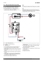
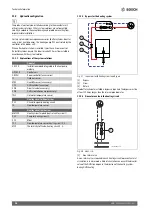
▶ Install the sensor on the coldest side of the house, normally facing
north. The sensor must be protected against direct sunlight, air vents
or other factors which could affect the temperature measurement.
The sensor must not be installed directly under the roof.
▶ Connect the outdoor temperature sensor T1 to the terminal T1 on the
installer module.
Fig. 9
Position of the outdoor temperature sensor
External inputs
NOTICE
Damage due to incorrect connection!
Connections intended for a different voltage or current can damage
electrical components.
▶ Only perform connections to the heat pump's external inputs which
are designed for 5 V and 1 mA.
▶ If an intermediate relay is required, use only relays with gold-plated
terminals.
The external inputs can be used for the remote control of certain
functions in the user interface.
Those functions which are activated by the external inputs are described
in the operating manual for the user interface.
The external inputs are connected either to a circuit breaker for manual
activation or a control device with a relay output for 5 V.
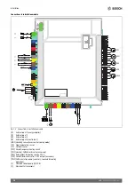
Connect the indoor unit
▶ Remove the lock of the control device.
▶ Feed the connecting lead through the cable feeds to the control
device.
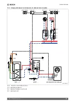
▶ Connect cable as shown in the wiring diagram.
▶ Reattach the cover of the control device and the front plate of the
indoor unit.
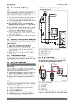
Fig. 10 Cable feeds
[1]
Cable feed for sensor, CAN-BUS and EMS-BUS
[2]
Cable feed for electrical connection
Considerations for three phase and single phase connections
NOTICE
Risk of product malfunction!
The fuse size should be appropriate to the selected setting for power
output of the electric booster heater (
table 6).
▶ If the indoor unit is connected with a single phase connection, fuse
sizes up to 50A are required.
▶ Always ensure that the selected power limitation fits the available
fuse size and cable cross-section during commissioning and
servicing.
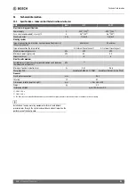
Fuse sizes for three phase and single phase connections:
Table 6 Required fuse sizes
The maximum power consumption of the electric heater can be limited
via the control unit. A stepwise limitation of 2/4/6/9kW (stand-alone
operation) and 2/4/6kW (during compressor operation) can be
selected. Depending on this setting, the required fuse size can be
reduced to the values shown in table 6. The correct setting for the
available fuse sizes must be ensured.
Comfort reduction may occur if the power output of the electric heater is
reduced.
1
/
2
H
(min 2m)
H
N
S
W
E
NW
NE
SW
SE
6 720 809 156-23.1I
Limitation of electric
heater
Required fuse size
for 3-phase
Required fuse size
for 1-phase
2kW
10A 16A
4kW
10A
25A
6kW
25A
32A
9kW
25A
50A
1
2


