


22
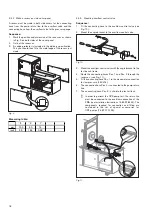
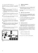
4.2
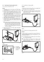
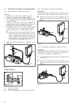
Connection of inductive proximity switch
Sequence:
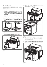
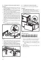
1.
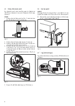
Pull the connecting cables of the inductive proximity switches
B11 and B12 through the distributor box’s X10 screwed
cable connection.
2.
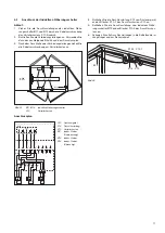
Join the connecting lines. To do so, use the following Fig. 22
and terminal diagram.
3.
After contacting the connecting lines, pull the screwed cable
connection on the distributor box.
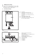
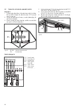
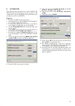
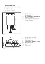
Fig. 22
B11-B13
Inductive proximity switch
X10
Distributor box
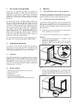
Terminal diagram
A10
Control device
X14
Connecting line
X10
Distributor box
B11
Induct. sensor
(drive side)
B12
Induct. sensor
B13
Induct. sensor
(Front side)
EPS
B11 B12
X10
B13
458777-22
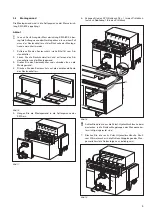
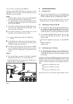
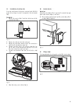
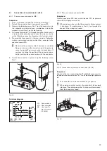
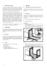
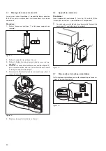
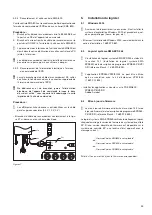
4.
Join connecting line X14 from the control device to the X10.1
connector of the connecting box X10.
5.
Join connecting line from the inductive proximity switch B13
to the X10.2 connector of the connecting box.
6.
Route all connecting lines into the cable ducts in the longitu-
dinal member and on the side frame.
Fig. 23
X14
X10
X10.1
X10.2
B13
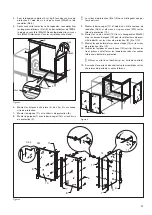
458777
-58
+
-
X14
A10
X10
B11
+
-
B12
B13
1
1
1
1
1
2
2
2
2
2
3
3
3
3
3
4
4
4
4
5
1
2
3
4
5
5
5
6
6
8
8
7
7
6
5
WH (ws)
BN (bn)
BN (bn)
BN (bn)
BN (bn)
BU (bl)
BU (bl)
BU (bl)
BK (sw)
BK (sw)
BK (sw)
GN (gn)
YE (ge)
GY (gr)
9
9
+
-
Summary of Contents for 1 687 001 845
Page 59: ...59 ...


