


16
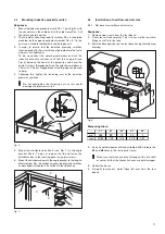
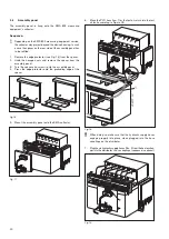
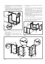
4.
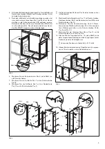
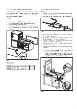
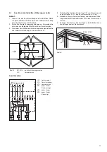
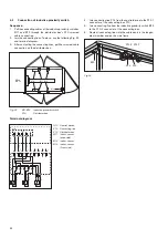
Bolt the upper longitudinal member Pos. 5 (see Fig.3) to both
protective frames using the hexagon bolts (M6x65) and
washers (A6,4).
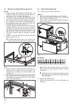
5.
Once all hexagon bolts (M6x65) have been tightened, the
lower longitudinal members Pos. 2 and Pos. 3 should be
clamped to the EPS collector using threaded pins. To this
end tighten the inner threaded pins (M5x10) – slightly – up to
the stop. Following this, the outer threaded pins (M5x20) are
turned in and tightened.
Fig. 3
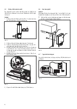
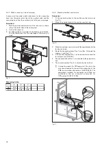
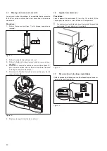
6.
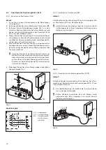
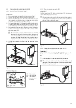
Mount the hinge strips Pos. 6 (see Fig. 4) to all protective plates.
7.
Mount handle strip Pos. 7 to protective plate Pos. 8.
8.
Mount handle strip Pos. 7 with the cover strip Pos: 12 to
protective plate Pos. 9.
i
The protective plates Pos.8 and Pos.9 differ in terms of width
only.
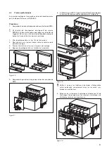
9.
Mount cover strip Pos.11 using hexagon bolts, washers
(A5,4) and hexagon nuts (M5) to the protective plate Pos.10.
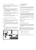
10. Bolt the contact screw Pos.12 (hexagon bolts M6x25) with
blind nuts Pos.13 for the inductive proximity switch to the
protective plates Pos.8, Pos.9 and Pos.10.
11. Mount the four eccentric latches Pos. 14 to the protective
plates Pos.8 and Pos.9.
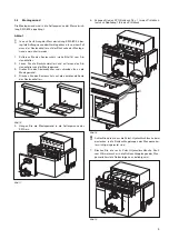
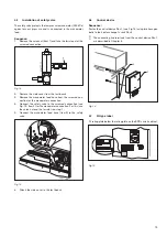
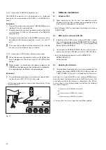
12. Insert the rubber buffer Pos.15 (see Fig. 5) into the intended
bores in the longitudinal members in the protective housing’
side frame.
i
To do so, use a lubricant (e.g. test oil)
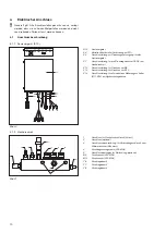
13. Mount the pre-assembled wing doors onto the specified door
hinges on the side frame
Fig. 5
Fig. 4
458777-45
5
2
3
M5x10
M6x65
A6,4
M5x20
458777
-47
15
15
15
8
9
10
6
6
7
8
10
11
6
7
11
9
14
458777-48
12
13
M5
A5,3
Summary of Contents for 1 687 001 845
Page 59: ...59 ...


