


19
3.5
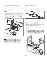
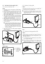
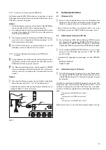
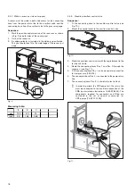
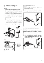
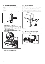
Installation of safety valve
The safety valve protects the low pressure manometer (250 kPa)
against excess pressure and is connected in the manometer
feed.
Sequence:
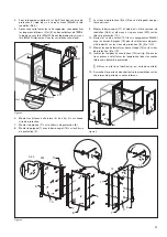
1.
Remove the union nut (Item 1) and take the ferrule out of the
screwed connection.
Fig. 12
2.
Remove the side cover from the test bench.
3.
Remove the manometer feed hose from the screwed con-
nection for the manometer connection.
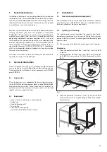
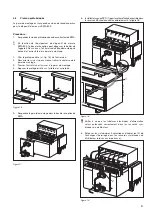
4.
Connect the safety valve to the screwed connection (see
Fig. 13, Item 2) for the manometer connection. For this, use
the union nut and the ferrule from step 1.
5.
Connect the manometer feed hose (Item3) to the safety
valve.
Fig. 13
6.
Attach the side cover to the test bench.
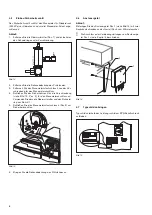
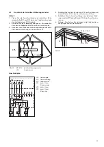
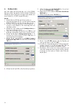
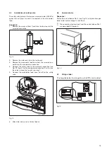
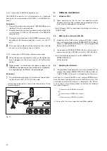
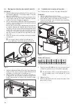
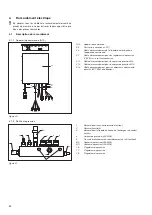
3.6
Control device
Sequence:
Fasten the control device Pos.1 (see Fig.14) using two hexagon
bolts to the heat exchanger’s rack Pos.2.
i
The connecting line terminals from the control device Pos.1
are described in Chapter 4.
Fig. 14
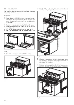
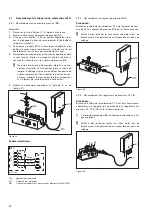
3.7
Fit type label
Fit rating plate below the rating plate on the EPS switch cabinet.
Fig.15
1
2
458777-14
458777-76
2
3
458777-75
1
Best.-Nr.
Geräte-Nr.
Nennspannung [V ]
Frequenz [Hz]
Nennleistung [kW ]
Nennstrom [A]
Strom d.gr. [A]
Bemessungsstrom [A]
Made in Germany
Phasenzahl
Typ
FD
Steuerspannung [V ]
Sicherung [A]
Druckluft [bar]
Wasser [bar] [L/h]
Schutzart [IP]
Gewicht [kg]
Stromlaufplan
Best. -Nr
.
Typ
.
Serien-Nr.
.
FD
Made in Germany
Rober
t B
o
sch GmbH
D-73207 Plochingen
1 687 001 845
CRS845
XXX
Pmax = 160 MPa
458777-73
Summary of Contents for 1 687 001 845
Page 59: ...59 ...


