background image

6

10

11

9

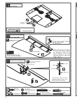
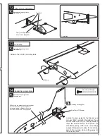
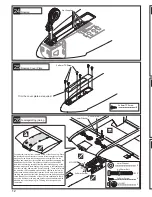
Aileron Servo installation 

Outer wing panel

Centre Wing

When  cutting  away  the  film,for 

the servo mount leave a gener-

ous  overhang  to  allow  for  the 

strong  shrinkage  of  the  Profilm 

(Orocover) when you finally iron 

it back in place.

A

B

Assemble left and right sides 

the same way.

Assemble left and right sides 

the same way.

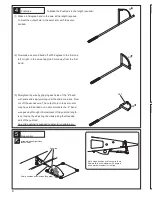
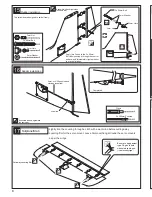
Be sure to apply instant type CA glue to

both sides of each hinges. 

(low viscosity type)

Cut away covering film.

Warning!

2.6 x12mm TP Screw

Be sure to glue securely.

This is Vital for safe flying!

11

23

22

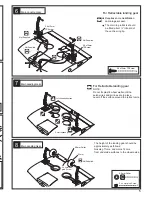
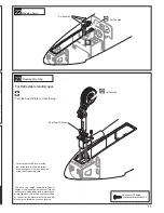
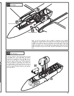
For Retractable landing gear.

Noseleg Servo

Noseleg Mounting

“Trim the Cover Plate to clear the leg.”

8

2.6 x12mm TP Screw

2

2 x 100mm 

Pushrod

2

Clevis

The  nose  leg  length  adjusted  to  give  a 

degree or two negative incidence or slightly 

nose down attitude when Intro is standing on 

a level surface. This will be easily overcome 

on take off by the elevator authority and will 

also help to eliminate bounce on landing.

2

2

4

2

3 x 50mm Bolt

3mm Nut

3mm Washer

3mm Horn

3mm

3mm Nut

3mm Washer

3mm Horn

3 x 50mm Bolt

3mm

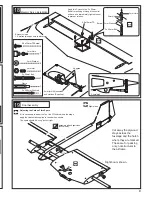
Apply thin cyano top and bottom and

immediately tighten the 3mm. nut to

prevent the 3mm. bolt rotating.

2

Aluminium joiner 

 6 x 40mm

Aluminium joiners 

6 x 40mm

Not Supplied.

Not Supplied.

2mm

Not Supplied.

4

2.6 x12mm TP Screw

2.6 x12mm TP Screw

2

Cut away part of the former at the

rear of the rails to allow the retract

unit steering arms to drop cleanly aft

of the retract mounting rails.

Summary of Contents for Sprint

Page 1: ...hose with insuf ficient building and flying experience This manual is for guidance only If you are unsure of any model building techniques seek help from an experienced model builder or contact Boomerang RC Jets LLC for assistance Jet models are dangerous if construction is carelessly or incorrectly carried out As the building assembly of this kit is out of our control after point of sale no liabi...

Page 2: ......

Page 3: ...ilm Not supplied Be sure to glue securely This is Vital for safe flying Apply thin Cyano glue to both sides of hinges to ensure good penetration Typical Servo Mount Flap Servo Installation Drill to suit your servos Not supplied Not supplied 2 6 x12mm TP Screw Cut away covering film For Main Landing Gear 3mm 3mm 3mm Nut 3mm Washer 4 2 6 x12mm TP Screw 1 1 2 1 3 x 50mm Bolt 3mm Nut 3mm Washer 3mm Ho...

Page 4: ...ly turning until the ends are in line Now cut off the excess wire The output hole in the servo arm may have to be drilled out to accommodate the Z bend wire passing through it Adjustment of the pushrod length is carried out by adjusting the clevis along the threaded part of the pushrod An extra pushrod is supplied to allow for possible error Pushrods Cut 90 90 90 5 Flap control Note hinge position...

Page 5: ... off shaded portion The main leg retracts should be fitted about inboard of the centre wing tip 2 2 2 6 Cut off shaded portion 55mm 5 2mm Collar 3 x 4mm grub Screw For Retractable landing gear Not Supplied NOTE Do not fix plastic wheel wells until the servo wires and air lines are in place Level off the surface around the retract units The height of the landing gear should be approximately as foll...

Page 6: ...me way Be sure to apply instant type CA glue to both sides of each hinges low viscosity type Cut away covering film Warning 2 6 x12mm TP Screw Be sure to glue securely This is Vital for safe flying 2 2 8 2 6 x12mm TP Screw 2 2 x 100mm Pushrod 2 Clevis T d n a o a 2 2 4 2 3 x 50mm Bolt 3mm Nut 3mm Washer 3mm Horn 3mm 3mm Nut 3mm Washer 3mm Horn 3 x 50mm Bolt 3mm Apply thin cyano top and bottom and ...

Page 7: ...il end you can use Midi servos for the rudders If you do this make up 6mm 1 4 liteply plates to raise the smaller servos and reduce the standard spacing of the servo mountings supplied Remember to allow for the shrink age of the covering when cutting away for the servo mounts 13 12 Aileron Servo installation Completed Outer wing Assemble left and right sides the same way Assemble left and right si...

Page 8: ...mm 14mm 54mm Completed Apply thin Cyano to the 3 x 50mm Bolt after pushing it through the control surface and immediately tighten the nut to prevent rotation 3mm or 4 40 pushrod and clevises supplied supplied Tailplane Stab Be sure to apply instant type CA glue to both sides of each hinges low viscosity type Cut away covering film Lightly iron the covering through a cloth with a warm iron before c...

Page 9: ...e and immediately tighten the nut to prevent rotation Supplied 3mm or 4 40 pushrods and clevises Supplied 1 2 x 200mm Pushrod 1 Clevis Extension lead 1 5 metres along booms to elevators Right boom shown Adjusting the Carbon Fibre Spars If it is necessary to adjust the fit of the C F spars within the wings apply the Heatshrink supplied to the spars as shown The spars should be snug but not tight Cu...

Page 10: ... 20mm Bolt 3 x 20mm Bolt Decrease size of top exit hole after wires are through to prevent the connector falling inside the fin Self adhesive 4 Self adhesive 1 1 2 5mm Hex Wrench Lock 3 x 10mm Bolt 4 3x10mm Bolt 3x10mm Bolt Wing Top Wing Locking ...

Page 11: ...ose down attitude when Intro is standing on a level surface This will be easily overcome on take off by the elevator authority and will also help to eliminate bounce on landing Not Supplied Not Supplied 2mm Not Supplied 4 2 6 x12mm TP Screw 2 6 x12mm TP Screw Cut away part of the former at the rear of the rails to allow the retract unit steering arms to drop cleanly aft of the retract mounting rai...

Page 12: ...a abd strip off the the film between the marks you have made Now strip the covering carefully from the underside edge only of the fuselage wing seat Before finally gluing the wing to the fuselage drill and inset the alloy dowels to the front of the wing These will slip into the parts No 1007 supplied which should be epoxied to the former using these dowels to adjust their position Drill a 4mm hole...

Page 13: ...floor for this A full tank of fuel weighs anything up to 8 Lbs 4 Kilos and in a negative G manoeuvre can exert consider able upward pull Clean up the front opening of the air intakes as necessary After carefully stripping away covering film from the small cutouts in the supper fuselage use the air intakes as a guide to how much covering to remove from each side of the fuselage opening up the airfl...

Page 14: ...RCE SPRINT 12849 849 849 USAF USAF USAF S P R I NT Boomerang SP RI NT S P R I NT Boomerang SP R I NT Boomerang S PR I N T S PRI N T Trim the hatch latch and if necessary adjust the front peg to achieve a good sliding fit A small smear of grease on the slots alloy buttons will help the hatch to slide easily into place ...

Page 15: ......

Page 16: ...irspeeds using slightly open throttle allowing a high angle of attack with virtually no risk of dropping a wing Mix in 10 down elevator with the flap movement to prevent the nose rising as it is applied If you have advanced mixing this should return to zero from half flap to full down flap SPRINT is capable of any aerobatics you care to try including spins both upright and inverted snaps tumbles r...

Page 17: ...so then it is highly unlikely to be the fault of the manufac turer Fly safely and avoid full throttle operation other than at low airspeeds RIC model jets are not toys If misused they can cause serious bodily hann and property damage Fly only in open areas and AMA Academy of Model Aeronautics or BMFA British Model Flying Associa tion or your country s approved flying sites Follow all manufacturer ...

Reviews: