DR-
8000 Video Switching Matrix
-14-
l
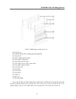
Notes for control board
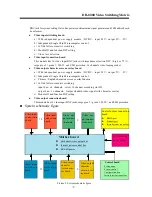
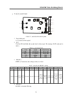
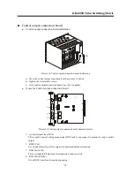
Picture 13, control board schematic picture
1. Programming port
It is for matrix software update
2. LED
The four LED should light when control board works properly. The meanings of LED are showed in
table 6:
Table 6, control board LED
3. DIP (SW1)
DIPSW1 is for matrix system setting, details are as below:
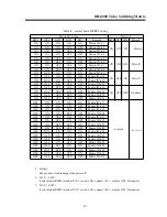
Table7 control board DIP SW1 setting
4. DIP (SW2)
DIP SW2 is for matrix ID setting
O
N
1
2
O
N
1
2
1
2
3
4
5
6
7
Label
remark
Normal status
POW -
-5V indicator
Always light
POW +
+5V indicator
Always light
COD
sending
Blink
STA
status
Blink
BIT 3
BIT 4
BIT 5
OFF
ON
OFF
ON
OFF
OFF
OFF
OFF
ON
OFF
ON
OFF
ON
BIT 6
BIT 7
BIT 2
Reserved
working
mode
Initial
ate
Reserved
Reserved
BIT 8
Chinese English
Display
dat e and
time
’
s
position
Display
menu
’
s
position
workin
g mode
debug
mode
KB and
P C users
do not
need to
login
KB and
P C users
need to
login
BIT 1

