


DR-
8000 Video Switching Matrix
-9-
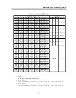
Table
5
corresponding board
l
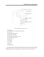
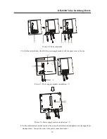
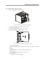
Matrix front side
Mother board, power supply module, Front cover, Control board, Video input switching board and
Video output character screen overlay board are on the matrix
’
s front side. The two thin folds at two end
edge are for fixing the matrix in the rack. (see picture 3)
There are four LEDs on each PCB board to indicate the status of the matrix or the board. All the boards
on the front side are hot swappable except the control board.
l
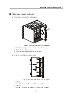
Matrix back side
Control output connection board, Video input connection board, Video output connection board, Back
cover and Power input jack are on the matrix
’
s back side. (see picture 4)
All the boards on the
backside are connection board, including
Control output connection board, Video input
connection board and Video output connection boar.
All the boards on the back side are hot swappable except the Control output connection board.
n
Mother board
l
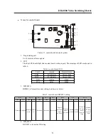
Notes for mother board
Mother board was preinstalled in the matrix. It has 18 standard slots and 2 special slots. Standard slots
are for Video input switching boar, Video input connection board, Video output character screen overlay
board and Video output connection board, each board has its own unique ID. It can accept 1-17 video
input modules(16-272 channels), 1-4 video output modules
(
16-64 channels
)
. Special slots are for
Control board and Control output connection board.
There are 64 channels video buses on the mother board for video output. The 64 video buses are inde-
pendent and well isolated therefore have high S/N ratio and good video output quality.
Mother has 4 high baud rate internal RS485 control buses. The control buses are accurate, precise and
reliable.
The mother board also has one power line for all the boards connected on it.
l
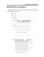
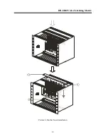
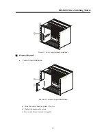
Mother board installation
The mother board was preinstalled in the matrix. Please follow the procedure to install/remove the
mother board when it is necessary. Put the mother board into the matrix according picture 6 showed then
fix on the connection bridge.
board
corresponding board
Control board
Control output connection board
Video input switching board
Video input connection board
Video output character screen overlay board
Video output connection board


