


10
2.2.3
Mounting the Unit
Prior to mounting the unit, this one shall be assigned with a unique range of addresses within the
polling loop. These addresses shall not coincide with addresses of any devices connected to the same
polling loop the unit is connected to. To get more detailed information on changing the unit addresses
please see 2.2.5 in this manual.
The unit shall be installed inside the premises to be protected.
The unit can be installed within mounting enclosures (fire and intrusion alarm cabinets, boxes,
etc.) on walls, behind suspended ceilings, or on other structures near the actuating appliances in the
premises protected against exposure to atmospheric precipitations and mechanical damage.
In case when various devices are arranged adjacently, vertical and horizontal distances between
them shall be at least 10 mm each.
The design of the unit doesn’t provide its operation in aggressive and / or dusty environments as
well as in explosion hazardous and flammable premises.
The unit shall be installed at a height suitable for operating and maintenance.
Installation and maintenance of the unit shall be carried out by professionals qualified for
Accident Prevention of Class II or higher.
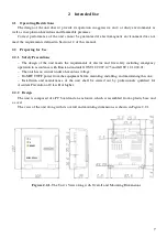
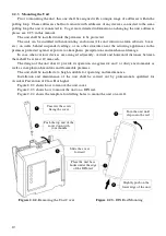
Figure 2.2.2 shows how to remove the unit cover.
Figure 2.2.3 shows how to mount the unit on a DIN rail.
Figure 2.2.4 shows the template for drilling holes to mount the unit on a wall.
Figure 2.2.2.
Removing the Unit Cover
Figure 2.2.3.
DIN Rail Mounting
Unscrew the screw
fixing the cover
Slide the cover
forward
Push the top end of the
cover down with
your thumbs
Slightly push on the
lower edge of the unit
Turn the unit until
clips onto the rail
Place the unit base
hooks under the edge
of the DIN-rail


