


7
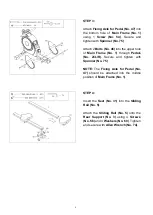
STEP 5:
Attach the
Sliding Rail (No. 5)
to
Main
Frame (No. 1)
using 6
Screws (No. 55)
and 6
Washers (No. 60)
. Tighten and
secure with
Allen Wrench (No. 74)
.
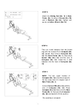
STEP 7:
NOTE:
The two upper buckles of
Computer (No. 32)
should be aligned to
the two upper slots of computer seat of
Main Frame (No. 1).
Connect
Sensor Wire (No. 34)
with the
wire of
Computer (No. 32)
. Place
Computer (No. 32)
back onto the
Main
Frame (No. 1)
, then push the
Computer
(No. 32)
downwards to fit into position.
The assembly is complete!
STEP 6:
Take out 2 AAA batteries from the plastic
bag with the manual. Push
Computer (No.
32)
upward, then remove
Computer (No.
32)
from
Main Frame (No. 1)
. Disconnect
Sensor Wire (No. 34)
and the wire of
Computer (No. 32)
. Install the 2 AAA
batteries into the back of
Computer (No.
32)
.


