background image


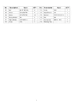
PARTS LIST


No. 

Description 

Spec. 

QTY 


No. 

Description 

Spec. 

QTY 

Main Frame 


34 

Sensor Wire 

L370 

1   

Front Stabilizer 


35 

Bearing 

Φ35*Φ10*11 

Rear Support   


36 

Bearing 

Φ30*Φ17*7 

Magnet Frame 


37 

Bearing 

35*17*16 

Sliding Rail 


38 

Bearing 

Φ26*Φ10*8 

Handlebar 


39 

Bearing 

Φ22*Φ8*7 

7L/R 

Seat Supporting 
L/R 


40 

Bearing Steel 

Φ17*46 

U Shape Bracket 


41 

Inertial Wheel 

Φ240*25    2.5kg 

Chain Cover L 


42 

Magnet 

25*10*5    2800 

10 

Chain Cover R 


43 

Inductor Seat   


11 

Tension Control 
Knob   

L=210 

44 

Volute Spring 

t0.5*22*5080 

12 

Plastic Lattice 
Magnet 

27*7 

45 

Axle Sleeve 

Φ42*44.5   

13 

Volute Spring 
Cover 

118.5*11.8 

46 

Bolt 

M12*160*S19 

14 

Mesh Belt Wheel 

Φ35*110 

47 

Fixing Axle for Pedal  Φ12*440 

15 

Outer PC Board   

Φ89*Φ16.5*0.5 

48 

Adjusting Screw 

M6    L45 

16 

PC Board   

Φ111*Φ16*0.5 

49 

U Shape Baffle 

30*10*1.5 2 

17 

Axle for Mesh Belt 
Wheel 

Φ22*133 

50 

Fixing Axle for Mesh 
Belt 

Φ5*43     

18 

Mesh Belt 

t1.5*22*2150 

51 

Spring 

Φ0.8*Φ8*60 65MN 

19 

Mesh Belt Pulley 

POM Φ42*Φ22*32 

52 

Spacer   

D8*Φ15*4     

20 

Wheel 

Φ40*92 POM 

53 

Screw 

M5*8 

21 

Casing Pipe for 
Idler Wheel 

Φ13*Φ8*78 ABS 

54 

Screw 

M6*10 

22L/R 

End Cap 

30*60 

55 

Screw 

M8*15*S6 

12 

23 

Foot Leveler 

M8 

56 

Screw 

M8*15*S6 

24 

End Cap 

70*30 

57 

Nut 

M6 

1


25 

Handlebar Seat 

104*50*18 PVC 

58 

Screw 

M5*15


3


26L/R 

Pedal L/R 

320*140*55 

59 

Screw 

M6*20 

27 

End Cap 

40*80*1.5 

60 

Washer 

d8*Φ16 *1.5 

24 

28 

Rubber Buffer 

Φ25.2*Φ22*15 

61 

Washer 

Φ20*Φ5*1.0 

29 

End Cap 

Φ25*1.5 PVC 

62 

Bolt 

M8*125*15 *S14 A 

30 

Foam Grip 

180 

63 

Nut 

M6*H6*S10 

31 

Seat 


64 

Nut 

M8*H7.5*S13 

32 

Computer 


1   


65 

Nut 

M10*1.0 H5 

33 

Magnet 

Φ11*3 

1   


66 

Nut   

M10*1.0 H3 


Summary of Contents for HC108A

Page 1: ...MAGNETIC ROWING MACHINE HC108A USER MANUAL IMPORTANT Please retain owner s manual for maintenance and adjustment instructions Your satisfaction is very important to us...

Page 2: ...equipment The equipment is designed for adult use only 4 Use the equipment on a solid flat level surface with a protective cover for your floor or carpet To ensure safety the equipment should have at...

Page 3: ...2 EXPLODED DIAGRAM HARDWARE PACKAGE...

Page 4: ...l 12 440 1 15 Outer PC Board 89 16 5 0 5 1 48 Adjusting Screw M6 L45 2 16 PC Board 111 16 0 5 1 49 U Shape Baffle 30 10 1 5 2 2 17 Axle for Mesh Belt Wheel 22 133 1 50 Fixing Axle for Mesh Belt 5 43 1...

Page 5: ...Nut M10 1 H8 S14 2 73 C clip d36 1 68 Screw ST4 2 20 8 6 74 Allen Wrench S6 1 69 Screw ST4 2 16 8 10 75 Spanner S13 14 15 17 19 1 70 Spring Washer 8 4 76 Nut M8 1 71 Wave Washer d10 15 0 3 2 77 Foot L...

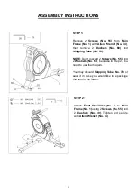
Page 6: ...en Wrench No 74 STEP 1 Remove 2 Screws No 55 from Main Frame No 1 with Allen Wrench No 74 then remove 2 Washers No 60 and Shipping Tube No 78 NOTE Don t discard 2 Screws No 55 and 2 Washers No 60 beca...

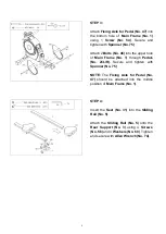
Page 7: ...le of Main Frame No 1 through Pedals No 26L R Secure and tighten with Spanner No 75 NOTE The Fixing Axle for Pedal No 47 should be attached into the middle position of Main Frame No 1 STEP 4 Insert th...

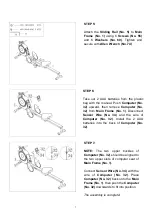
Page 8: ...No 1 Connect Sensor Wire No 34 with the wire of Computer No 32 Place Computer No 32 back onto the Main Frame No 1 then push the Computer No 32 downwards to fit into position The assembly is complete...

Page 9: ...ring use you should adjust the foot levelers located beneath the rear support Rotate Foot Levelers No 23 clockwise until it sits level with the surface that the rower is on When you have finished adju...

Page 10: ...d do not mix old and new batteries After the replacement connect Sensor Wire No 34 to the wire of Computer No 32 and put Computer No 32 back onto the Main Frame No 1 Dispose or recycle batteries accor...

Page 11: ...ton until SCAN appears The display will rotate through the six functions in the following order TIME DISTANCE CALORIES COUNT TOTAL COUNT and RPM Each display will be held for 6 seconds TIME Counts the...

Page 12: ...a username and password 12 2 How to connect device 12 2 1 Search equipment 13 2 2 Connecting equipment 13 2 3 Connect successfully 14 3 Operational Instructions 14 3 1 Motion setting 14 3 2 Select mo...

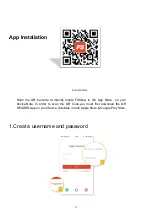
Page 13: ...d password Scan the QR barcode to directly locate FitShow in the App Store on your device Note In order to scan the QR Code you must first download the QR READER App on your device Available in both A...

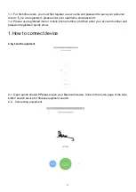
Page 14: ...e and password 1 2 Please use registered mail or mobile phone number and then enter your account number and password registered sports show 1 How to connect device 2 1 Search equipment 2 1 Open sports...

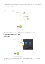
Page 15: ...nt can be connected 2 3 Connect successfully 2 3 After a successful connection can be selected according to the mode of exercise you need to 2 Operational Instructions 3 1 Motion setting 3 1 Change is...

Page 16: ...ll display two modes you can choose any mode according to your needs and then click the start button for movement 3 3 Start exercis When you start the exercise the mileage in your exercise when used w...

Page 17: ...se limits are designed to provide reasonable protection against harmful interference in a residential installation This equipment generates uses and can radiate radio frequency energy and if not insta...

Reviews: