background image


2


STEP #1 – Disconnect Power 

Disconnect the motor wires from the power source before working on the motor. 
The motor or gearmotor should be cooled off to room temperature. 


WARNING


Failure to disconnect the motor wires from the 
power source before inspecting or replacing 
brushes can result in personal injury. 


STEP #2 – Remove Two Brush Caps 

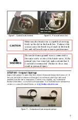
Refer to Figure 1 for the location of the two brush caps.  The plastic brush caps 
are held in place with screw threads.  Unscrew the brush caps using the largest 
possible slotted screwdriver tip and remove them. 


CAUTION 

The brush caps are made of plastic and are installed 
tightly.  Using a small screwdriver to remove them 
will damage the slot. 


STEP #3 – Remove Brush Springs 

After the brush caps are removed from each side 
of the motor, the brush box assemblies can be seen 
inside each of the two openings.  The brushes are 
retained by constant-force, roll-type springs.  The 
springs must be removed before the brushes can 
be removed.  To remove a spring, first locate the 
flat part of the spring, which points outward (see 
Figure 3).  

WARNING:  Wear safety glasses! 


Figure 3 – Flat part of spring. 

Brush Caps 
(one on each side) 

Figure 1 – Location of the Brush Caps 

Figure 2 – Use a large screwdriver. 

Flat part of spring 

Summary of Contents for 33A

Page 1: ...ts a constant force on the brushes even as they wear and get shorter By contrast the force exerted by a coiled spring diminishes as the brushes get shorter and the spring approaches its uncompressed length Reduced force on the brushes can cause them to hop on the commutator and wear faster The roll type spring is a superior design Installing the roll type springs correctly is critical in order to ...

Page 2: ...crewdriver tip and remove them CAUTION The brush caps are made of plastic and are installed tightly Using a small screwdriver to remove them will damage the slot STEP 3 Remove Brush Springs After the brush caps are removed from each side of the motor the brush box assemblies can be seen inside each of the two openings The brushes are retained by constant force roll type springs The springs must be...

Page 3: ...side of the motor or gearmotor STEP 4 Inspect Brushes It is not necessary to disconnect the brush wires just to inspect the brushes Insert a small screwdriver under the brush wire and pull the brush out of the brush box With the brush wire still connected to the brush box measure the length of the brush from the point where the wire merges with the brush to the end of the brush that contacts the c...

Page 4: ... screw head and remove the brush Repeat this procedure for the other brush STEP 6 Clean Out Brush Dust Excessive carbon dust will accumulate inside the motor endshield over time and should be removed periodically to allow normal operation Partial disassembly and cleaning is best However carefully applying compressed air alternately through each of the open brush cap holes may provide adequate clea...

Page 5: ...to do so may result in personal injury STEP 8 Inspect Springs Inspect the springs to make sure they weren t damaged during their removal If they are uncoiled or otherwise damaged record the product type and serial number from the motor nameplate Contact your supplier any Authorized Bodine Distributor or our Service Department You will find more information on how to contact Bodine Electric at www ...

Page 6: ...bracket back out of the brush box until the hooks latch around the edge of the brush box Release the pliers If the spring bracket is properly seated it will be lying flat against the brush box wall If it is cocked to one side it is improperly seated release the spring and reassemble it again Important As a final check apply slight pressure on the spring bracket in the direction away from the brush...

Page 7: ...ossible screwdriver STEP 11 Connect to Power Reconnect the drive to the power source and test for proper operation New brushes may be seated by running the motor or gearmotor in at no load Proper seating is required for lowest brush noise level All information and data contained in this document are subject to change without notice Please contact our Technical Support staff in Chicago or an Author...

Page 8: ...ley Place Chicago Illinois 60618 U S A TEL 773 478 3515 FAX 773 478 3232 www bodine electric com Inspecting and Replacing Brushes in a Bodine Type 33A 42A and 32A motor or gearmotor Lit P N 07481063A1 Bodine 2007 Page 8 of 8 851 628 Rev A ...

Reviews: