Page 18
Atmospheric Gas
SECTION VIII: PARTS LIST (cont.)
2
6
3
5
4
2
1
1
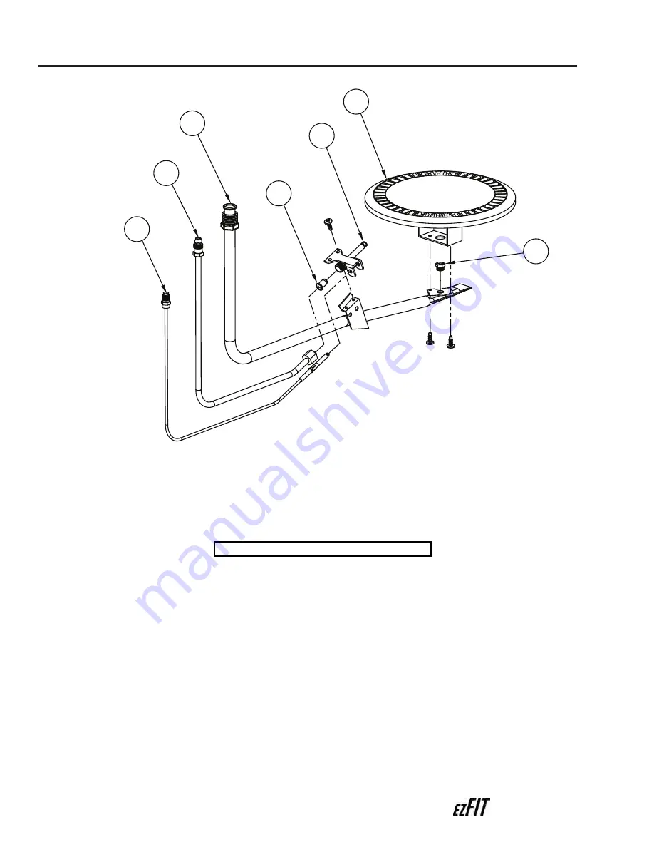
Burner
2
Pilot Kit
3
Main Burner Tube
4
Pilot Tube
5
Thermocouple
6
Orifice (Natural or LP)
P
Pa
arrtt D
De
es
sc
crriip
pttiio
on
n
Figure 8:
ezFIT Burner Parts
Table 5:
ezFIT Burner Parts


