35
The main power (A) and the stepper motors (C,H,I,
and J) have to be connected correctly. Improper
connection can permanently damage the board. If you are
unsure about the connection, the internet is a good resource
and has a great deal of information on the Ramps1.4.
The connections are:
A. Main Power supply
F. Z-max limit switch
B. Extruder power
G. Extruder sensor
C. Extruder stepper motor
H. X stepper motor
D. X-min limit switch
I. Y stepper motor
E. Y-min limit switch
J. Z stepper motors
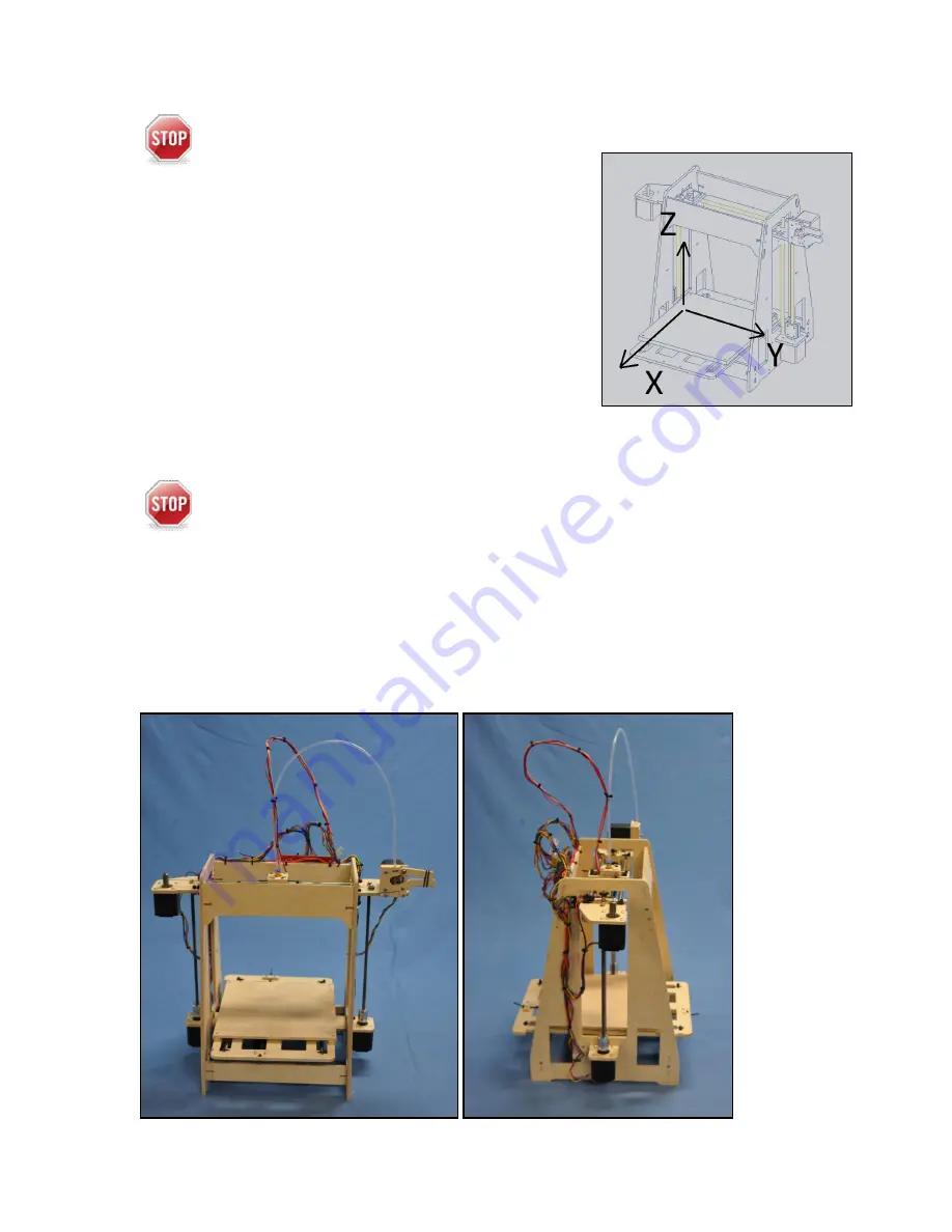
Wire Routing With Nylon Ties
There are drilled holes in the frame and small extra small nylon ties included in
the kit to secure the wires. Several sets of wires will need clearance to move with the Y-
assembly. They included the:
Extruder and Y stepper motor wires.
Z limit switch wires.
The Extruder heater and sensor wires.
While there are several ways to correctly route the wires, below are pictures of typical
wire routing. I have found the key is to start from the controller move outward.


