background image

Form 

No. 

1550-69 

r4/20/18          © 

2018 

Bobrick 

Washroom 

Equipment, 

Inc.          Printed 

in 

U.S.A.

Page 6

67-1/2''

(171cm)

41''

(104cm)

64''

(163cm)

Panel

Centerlines

Floor Anchors

14-3/4''

(37cm)

18''

(46cm)

Wall Post

54-1/2''

(138cm)

27-1/2''

(69cm)

64''

(163cm)

18''

(46cm)

Panel

Centerline

64''

(163cm)

43''

(109cm)

Floor Anchors

18''

(46cm)

Stile

Centerline

64''

(163cm)

18''

(46cm)

Panel Centerline

64''

(163cm)

Floor Anchors

Panel Centerline

18''

(46cm)

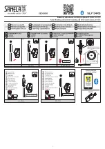
A.  Measure and mark the locations of centerlines for all 

the stiles and panels on walls.

B.  Using the wall brackets as templates, measure 

and mark the location of all mounting holes, plumb 
according to dimensions shown in illustrations (Fig. 
3a, 3b, 3c).

C.  Use #19 (.166) drill bit (4.2mm) for 2" (50mm) deep 

pilot holes into adequate wall backing.

D.  Secure wall brackets with 1002495 screws.

INSTALL WALL BRACKETS AND WALL POSTS

STEP 3

Fig. 3a: Front-Entry Corner Layout with  


Wall Post.

Fig. 3b: Overhead-Braced Alcove Closed  


 Layout.

Fig. 3c: Floor-Anchored or Ceiling-Hung  


Alcove Open Layout.

These mounting points require wall backing.

Obtain Dimension from Bobrick Layout Sheet.
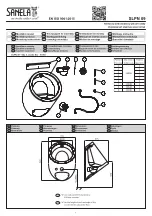
WALL POST #1002250

A.  Determine the location and hole of the 1" x 1-1/2" 

(25 x 40mm) stainless steel wall post being installed. 
Outside edge of wall post to be in-line with outside 
edge of keeping stile. The wall must have adequate 
backing at mounting location to support door hung in 
place.

B.  Install wall post at given height and fasten, plumb in 

both directions to wall with (5) wall screws provided. 
Install (2) post end caps and (5) mounting hole plugs.

C.  Attach door with through bolts provided as you install 

door(s) on pages 13.

Summary of Contents for AccentSeries 1530

Page 1: ...STRUCTIONS HIGH PRESSURE LAMINATE HPL TOILET PARTITIONS 1550 MetroSeriesTM and 1530 AccentSeriesTM FLOOR ANCHORED OVERHEAD BRACED CEILING HUNG IMPORTANT Storage and Handling Information on last page For faster easier installation please review these instructions thoroughly prior to installation ...

Page 2: ...0 Install Door Hardware Page 11 11 Install Shoes Page 12 12 Finish And Cleanup Page 12 A 1530 and 1550 64 option uses stainless steel hardware B Organize components with appropriate hardware C When calculating distances to centerlines all panels stiles and doors are 1 25mm thick D Look for panel to stile offsets indicated on the layout sheets PREPARATION RECOMMENDED TOOLS CAUTION Be sure to use pr...

Page 3: ...ut Outswing Door Fig 1c Floor Anchored or Ceiling Hung Alcove Closed Layout Inswing Door NOTE The center stile is perpendicular to panel NOTE The stiles are in line with panel NOTE The center stile is perpendicular to panel LEGEND Obtain Dimension from Bobrick Layout Sheet Floor Anchored Stile Drilling Table Overhead Braced Series Standard 64 Option Floor Anchored Series Ceiling Hung Stiles Ceilin...

Page 4: ...ng is applied All structural framing is to be furnished by others For Bobrick recommendations refer to Bobrick Form No TB 32 A Drill 7 16 11mm diameter hole through structural beam Insert threaded rod through hole in beam Rod is furnished standard 6 150mm length Longer rods should be purchased locally if required B Drop a bevel washer and lock washer over rod Screw on one hex nut C Install second ...

Page 5: ...nt Entry Corner Layout NOTE Adequate wall backing is required High quality drill bit is suggested for drilling into steel core stiles EXAMPLE BRACKET APPLICATIONS 1002495 12 x 2 M5 5 x 50mm Wall Screws 1002500 12 x 3 4 M5 5 x 19mm Panel Stile Screws 19 166 x 3 4 4 2 x 19mm For attachment of brackets to panels Do not through drill 3 16 x 3 4 4 7 x 19mm For attachment of U brackets L brackets or Y b...

Page 6: ... holes into adequate wall backing D Secure wall brackets with 1002495 screws INSTALL WALL BRACKETS AND WALL POSTS STEP 3 Fig 3a Front Entry Corner Layout with Wall Post Fig 3b Overhead Braced Alcove Closed Layout Fig 3c Floor Anchored or Ceiling Hung Alcove Open Layout These mounting points require wall backing Obtain Dimension from Bobrick Layout Sheet WALL POST 1002250 A Determine the location a...

Page 7: ...ment CAUTION Panel centerline is not always on the stile centerline Refer to Bobrick Layout Sheets for panel offsets A Measure and mark the centerlines for three 3 U or L brackets per stile B Using U or L bracket as a template mark the location of all mounting holes C For U or L brackets attached to steel core stiles use a high quality drill bit 3 16 4 7mm for 3 4 19mm deep pilot holes D Caution D...

Page 8: ... shims between panels and wall E Set door openings to be square plumb and true per Bobrick Layout Sheets F Tighten hex nuts on stile anchoring system G Secure panels to wall brackets using 14 x 5 8 screws or 1002500 for stainless steel option INSTALL STILES AND SET DOOR OPENINGS STEP 6 A Install leveling bolt into stile B While stile is laying flat rotate leveling bolt so that overall stile dimens...

Page 9: ...easure from wall to outside edge of stile less 1 8 3mm B Place headrail over top of stiles C Drill 19 166 x 3 4 4 2 x 19mm pilot holes through interior sides of headrail into stiles Fasten headrail to stile using 12 x 7 16 M5 5 x 10mm screws D For corner and alcove layouts cut return headrail 1 8 less than dimension from inner edge of headrail to the back wall E Using headrail L bracket as a templ...

Page 10: ...plastic cam on upper stile hinge half E Lift door and position onto upper stile hinge half Door should be hanging securely on upper hinge F Insert remaining hinge pin in lower door and hinge half and mount to door To Increase or Decrease Opening of Door A Alignment tabs have been formed into the cam and plastic hinge bushing B Lift door to limit of upward travel approximately 1 2 While door is lif...

Page 11: ...g door bumper Fig 9h to panel or door at location that prevents door from hitting panel on the inswing Fig 9f Mounting Location of Latch Keeper with Emergency Access Fig 9h Robe Hook and Bumper Fig 9g Perpendicular Stile Mounting Location of Latch Keeper Fig 9i Mounting Location of Latch and Keeper with Emergency Access Outswing A Mount latches and keepers as shown Fig 9f 9i using screws 1002500 1...

Page 12: ...ly detail reference diagram on Page 4 C Shoes accommodate 1 thick or 3 4 thick stiles For 1 thick stiles orient shoe with 3 16 wide flange return against faces and edge of stile D Standard Stile Installation See Fig 10 Open end of shoe and slide onto bottom of stile trapping bottom flange under shoe retainer Close open end of shoe overlapping so holes are aligned Install flat head retaining screw ...

Page 13: ...Form No 1550 69 r4 20 18 2018 Bobrick Washroom Equipment Inc Printed in U S A ...

Page 14: ...el 818 982 9600 Fax 818 503 1102 New York 200 Commerce Drive Clifton Park NY 12065 1350 Tel 518 877 7444 Fax 518 877 5029 or e mail customerservice bobrick com In Canada BOBRICK WASHROOM EQUIPMENT COMPANY 45 Rolark Drive Scarborough Ontario M1R 3B1 Eastern Canada Tel 877 423 6555 Fax 877 423 8555 Western Canada Tel 877 423 6444 Fax 877 423 8444 or e mail customerservice bobrick com ...

Reviews: