background image

Overview

The socket is located between the front seats.

Information

Observe the following when connecting:

Do not use force when plugging the con‐
nector into the USB interface.

Do not connect devices such as fans or
lights to the USB interface.

Do not connect USB hard drives.

Do not use the USB interface for recharg‐
ing external devices.

Cargo area

Cargo cover

Information

WARNING
Loose objects in the car's interior can be

thrown into the car's interior while driving, e.g.
in the event of an accident or during braking
and evasive maneuvers. There is risk of inju‐
ries. Secure loose objects in the car's inte‐
rior.◀

General information

The cargo cover is in two parts. This can be re‐
moved to load bulky luggage.

Removing

Rear cover

1.

Detach the retaining straps at the tailgate.

2.

Pry cover up a bit, arrow 1, and pull out of
the brackets toward the back, arrow 2.

Front cover

1.

Push cover out of the bracket upward on
both sides, arrow 1.

2.

Pull cover out of the bracket toward the
rear on both sides, arrow 2.

Installing

Proceed in the reverse order to reinstall. The
cargo covers must snap audibly into place on
their respective holders.

Cargo floor panel

General information

The cargo floor panel can be removed to stow
unwieldy luggage.

Seite 157

Interior equipment

Controls

157

Online Edition for Part no. 01 40 2 964 303 - VI/15

Summary of Contents for X1 2015

Page 1: ...Owner s Manual for Vehicle The Ultimate Driving Machine THE BMW X1 OWNER S MANUAL Contents A Z Online Edition for Part no 01 40 2 964 303 VI 15 ...

Page 2: ......

Page 3: ... available in your BMW The manual also contains information designed to en hance operating reliability and road safety and to contribute to maintaining the value of your BMW Any updates made after the editorial deadline can be found in the appendix of the printed Owner s Handbook for Vehicle Supplementary information can be found in the additional bro chures in the onboard literature We wish you a...

Page 4: ...ich Germany Reprinting including excerpts only with the written consent of BMW AG Munich US English VI 15 07 15 490 Printed on environmentally friendly paper bleached without chlorine suitable for recycling Online Edition for Part no 01 40 2 964 303 VI 15 ...

Page 5: ...isplays 97 Lights 102 Safety 120 Driving stability control systems 126 Driving comfort 144 Climate control 151 Interior equipment 160 Storage compartments Driving tips 168 Things to remember when driving 172 Loading 175 Saving fuel Mobility 182 Refueling 184 Fuel 186 Wheels and tires 197 Engine compartment 199 Engine oil 202 Coolant 204 Maintenance 206 Replacing components 217 Breakdown assistance...

Page 6: ...an app Additional information on the Internet www bmw com bmw_drivers_guide Symbols and displays Symbols in the Owner s Manual Indicates precautions that must be followed precisely in order to avoid the possibility of personal injury and serious damage to the vehicle Marks the end of a specific item of information Refers to measures that can be taken to help protect the environment Identifies disp...

Page 7: ...gistration require ments applying in the country of first delivery also known as homologation If your vehicle is to be operated in a different country it might be necessary to adapt your vehicle to potentially differing operating conditions and permit re quirements If your vehicle does not comply with the homologation requirements in a cer tain country you may not be able to lodge war ranty claims...

Page 8: ...anty Detailed information about these warranties is listed in the Service and Warranty Information Booklet for US models or in the Warranty and Service Guide Booklet for Canadian models Your vehicle has been specifically adapted and designed to meet the particular operating con ditions and homologation requirements in your country and continental region in order to de liver the full driving pleasu...

Page 9: ...ehicle emergency locating you can transmit certain vehicle data from the vehicle Event Data Recorder EDR This vehicle is equipped with an event data re corder EDR The main purpose of an EDR is to record in certain crash or near crash like situa tions such as an air bag deployment or hitting a road obstacle data that will assist in under standing how a vehicle s systems performed The EDR is designe...

Page 10: ...nd if it finds that a safety defect exists in a group of vehicles it may order a recall and remedy campaign However NHTSA cannot become involved in individual problems between you your dealer or BMW of North America LLC To contact NHTSA you may call the Vehicle Safety Hotline toll free at 1 888 327 4236 TTY 1 800 424 9153 go to http www safercar gov or write to Administrator NHTSA 400 Seventh Stre...

Page 11: ...Information 11 Online Edition for Part no 01 40 2 964 303 VI 15 ...

Page 12: ...Online Edition for Part no 01 40 2 964 303 VI 15 ...

Page 13: ...iews of buttons switches and displays are intended to familiarize you with your vehicle You will also become quickly acquainted with the available control concepts and options Online Edition for Part no 01 40 2 964 303 VI 15 ...

Page 14: ...s to safety related functions and systems The respectively applicable country provisions must be observed when using the respective features and systems All around the steering wheel 1 Rear window safety switch 49 2 Power windows 48 3 Exterior mirror operation 60 4 Central locking system Unlocking 39 Lock 39 5 Lights Front fog lights 100 Lights off Daytime running lights 99 Parking lights 97 Low b...

Page 15: ...wiper 76 Cleaning rear window 76 10 Start stop the engine and switch the ignition on off 69 Auto Start Stop function 70 11 Steering wheel buttons right Entertainment source Volume Voice activation 26 Telephone Thumbwheel for selection lists 90 12 Horn total area 13 Steering wheel heating 62 14 Adjust steering wheel 62 15 Steering wheel buttons left Cruise control on off interrupt ing 132 Active Cr...

Page 16: ... Glove compartment 160 6 Climate control 144 7 Transmission selector lever 77 8 Controller with buttons 19 9 Parking brake 72 10 DSC Dynamic Stability Con trol 120 Driving Dynamics Control 124 PDC Park Distance Control 135 Rearview camera 137 Parking assistant 140 HDC Hill Descent Control 122 At a glance Cockpit 16 Online Edition for Part no 01 40 2 964 303 VI 15 ...

Page 17: ...er 1 Intelligent Emergency Re quest 217 2 Glass sunroof 49 3 Indicator lamp front seat pas senger airbag 104 4 Reading lights 100 5 Interior lights 100 Cockpit At a glance 17 Online Edition for Part no 01 40 2 964 303 VI 15 ...

Page 18: ...is risk of an accident Only use the systems or devices when the traffic situation allows If necessary stop and use the systems and devices while the vehicle is stationary Control elements at a glance Control elements 1 Control Display 2 Controller with buttons and depending on the equipment version with touchpad Control Display Information To clean the Control Display follow the care instructions ...

Page 19: ...rections Buttons on controller Press button Function MENU Open the main menu RADIO Opens the Radio menu MEDIA Opens the Multimedia menu NAV Opens the Navigation menu TEL Opens the phone menu BACK Displays the previous display OPTION Opens the Options menu Controller without navigation system The buttons can be used to open the menus directly The controller can be used to select menu items and ente...

Page 20: ...items can be selected 1 Turn the controller until the desired menu item is highlighted 2 Press the controller Menu items in the Owner s Manual In the Owner s Manual menu items that can be selected are set in quotation marks e g Settings Changing between panels After a menu item is selected e g Radio a new panel is displayed Panels can overlap Move the controller to the left Closes current display ...

Page 21: ... displayed 3 Press the controller Activating deactivating the functions Several menu items are preceded by a check box It indicates whether the function is acti vated or deactivated Selecting the menu item activates or deactivates the function Function is activated Function is deactivated Touchpad Some iDrive functions can be operated using the touchpad on the controller Selecting functions 1 Sett...

Page 22: ...o the right in the lower area of the touchpad Using interactive map and Internet Via touch pad move the interactive map in the navigation system and Internet sites Function Controls Move interactive map or Internet sites Swipe into re spective direc tion Enlarge shrink interactive map or Internet sites Drag in or out on the touchpad with fingers Display the menu or open a link in the Internet Tap ...

Page 23: ...l flashes network search Wireless network is not available Bluetooth is switched on Roaming is active Symbol Meaning Text message was received Check the SIM card SIM card is blocked SIM card is missing Enter PIN Entertainment symbols Symbol Meaning CD DVD player AUX IN port USB audio interface Mobile phone audio interface Additional symbols Symbol Meaning Spoken instructions are turned off Split s...

Page 24: ...desired button until a signal sounds Running a function Press button The function will work immediately This means e g that the number is dialed when a phone number is selected Displaying the button assignment Touch buttons with bare fingers Do not wear gloves or use objects The key assignment is displayed at top edge of screen Deleting the button assignments 1 Press buttons 1 and 8 simultaneously...

Page 25: ...3 OK confirm the entry Symbol Function Press the controller delete the let ter or number Press the controller for an extended period delete all letters or numbers Switching between cases letters and numbers Depending on the menu you can switch be tween entering upper and lower case letters and numbers Symbol Function Enter the letters Enter the numbers or Tip controller up Without navigation syste...

Page 26: ...oken commands can be identi fied Set the language refer to page 94 Using voice activation Activating the voice activation system 1 Press button on the steering wheel 2 Wait for the signal 3 Say the command A command that is recognized by the voice activation system is announced and dis played in the instrument cluster This symbol in the instrument cluster indi cates that the voice activation syste...

Page 27: ...gs can also be started via a short command 1 Turn on the Entertainment sound output if needed 2 Press button on the steering wheel 3 Tone Setting the voice dialog Set system to standard dialog or use a short version The short version of the voice dialog plays back short messages in abbreviated form 1 Settings 2 Language Units 3 Speech type 4 Select setting Adjusting the volume Turn the volume butt...

Page 28: ...sis and speed Always say commands in the language of the voice activation system Keep the doors windows and glass sun roof closed to prevent noise interference Avoid making other noise in the vehicle while speaking At a glance Voice activation system 28 Online Edition for Part no 01 40 2 964 303 VI 15 ...

Page 29: ...ck Reference Guide provides informa tion how to operate the car how to use basic vehicle functions or what to do in case of a breakdown This information can also be dis played while driving Search by images Image search provides information and de scriptions This is helpful when the terminol ogy for a feature is not at hand Owner s Manual Search for information and descriptions by en tering terms ...

Page 30: ...function and the Owner s Manual To switch from a function e g radio to the Owner s Manual on the Control Display and to alternate between the two displays 1 Press button or move the controller to the right repeatedly until the Options menu is displayed 2 Display Owner s Manual 3 Select the desired page in the Owner s Manual 4 Press button again to return to last displayed function 5 Press button t...

Page 31: ...Integrated Owner s Manual in the vehicle At a glance 31 Online Edition for Part no 01 40 2 964 303 VI 15 ...

Page 32: ...Online Edition for Part no 01 40 2 964 303 VI 15 ...

Page 33: ...vide you with information that will give you complete control of your vehicle All features and accessories that are useful for driving and your safety comfort and convenience are described here Online Edition for Part no 01 40 2 964 303 VI 15 ...

Page 34: ...trols with integrated key Every remote control holds a replaceable bat tery You may set the key functions depending on the optional features and country specific ver sion For Settings refer to page 45 The vehicle stores personal settings for every remote control Personal Profile refer to page 35 The remote controls hold information on re quired maintenance Service data in the re mote control refer...

Page 35: ...nce from radio transmissions through mobile devices in close proximity to remote control Interference of radio transmission by charger while charging items such as mo bile devices in the vehicle A Check Control message is displayed if an at tempt is made to switch on the ignition or start the engine Starting the engine via emergency detection of the remote control Steptronic transmission if a resp...

Page 36: ...mote control in use a dif ferent profile may be activated About iDrive 1 Settings 2 Profiles 3 Select a profile All settings stored in the called up profile are automatically applied The called up profile is assigned to the re mote control being used at the time If the profile is already assigned to a differ ent remote control this profile will apply to both remote controls It cannot be differen t...

Page 37: ...t The guest profile cannot be renamed It is not assigned to the current remote control Display profile list during start The profile list can be displayed during each start to select the desired profile On the Control Display 1 Settings 2 Profiles 3 Open Options 4 Display user list at startup Using the remote control Information WARNING People or animals in the vehicle can lock the doors from the ...

Page 38: ...ou can trigger the alarm system if you find yourself in a dangerous situation Press button on the remote control for at least 3 seconds To switch off the alarm press any button Unlocking the tailgate With automatic tailgate operation To avoid locking it into the vehicle do not place the remote control in the cargo area Press button on the remote control for approx 1 second The tailgate opens sligh...

Page 39: ...tion Any unauthorized modifications or changes to these devices could void the user s authority to operate this equipment Without remote control From the outside WARNING Unlocking from the inside is only possi ble with special knowledge If people must spend a longer time in the vehi cle while it is very hot or cold outside there is risk of injuries or danger to life Do not lock the vehicle from th...

Page 40: ...then pull the door handle above the armrest Front doors pull the door handle on the door to open the door The other doors re main locked Back doors pull twice on the door handle on the door to be opened the first time un locks the door the second time opens it The other doors remain locked Tailgate Information To avoid locking it into the vehicle do not place the remote control in the cargo area O...

Page 41: ...g When adjusting the opening height ensure that there is a clearance of at least 4 in 10 cm above the tailgate 1 Settings 2 Tailgate 3 Turn the controller until the desired open ing height is selected Opening CAUTION The tailgate swings back and up when it opens There is risk of property damage Make sure that the area of movement of the tailgate is clear during opening and closing Press button on ...

Page 42: ...hicle do not place the remote control in the cargo area Pressing the button again stops the mo tion Press button on tailgate s exterior Pressing the button again stops the mo tion Press button in the driver s door and keep it pressed Releasing the button stops window roof movement The remote control must be located in the interior for this function An acoustic signal sounds and the tailgate closes...

Page 43: ...the doors The next unlocking and locking cycle is not possible until after approx 2 seconds The engine can only be started if the re mote control is in the vehicle Unlocking Grasp the door handle on the driver s or front passenger door completely arrow This corresponds with pressing the button on the remote control Locking Touch the surface on the door handle of the driver s or front passenger doo...

Page 44: ... automatic tailgate operation it can also be closed with no touch activation Two sensors detect a forward directed foot motion in the center of the area at the rear of the car and the trunk lid opens and or closes Foot movement to be carried out WARNING During no contact activation vehicle parts may be touched e g hot exhaust sys tem There is risk of injuries With the foot mo tion make sure there ...

Page 45: ...ening and closing CAUTION The tailgate swings back and up when it opens There is risk of property damage Make sure that the area of movement of the tailgate is clear during opening and closing Malfunction Remote control detection by the vehicle can among others be malfunctioning under the fol lowing circumstances The battery of the remote control is dis charged Replace the battery refer to page 35...

Page 46: ...s automatically after you drive off Retrieving the seat and mirror settings The driver s seat and exterior mirror positions used last are stored for the remote control cur rently used When the vehicle is unlocked these positions are automatically retrieved if this function was activated WARNING There is risk of jamming when moving the seats There is risk of injuries or risk of property damage Make...

Page 47: ...locking Doors hood or tailgate are not correctly closed Correctly closed access points are secured After 10 seconds the indicator lamp flashes continuously Interior motion sen sor and tilt alarm sensor are not active When the still open access is closed inte rior motion sensor and tilt alarm sensor will be switched on The indicator lamp goes out after unlock ing The vehicle has not been tampered w...

Page 48: ...rs or windows Shifting the selector lever into neutral Using vehicle equipment There is risk of accidents or injuries Do not leave children or animals unattended in the ve hicle Carry remote control along when exiting and lock the vehicle Overview Opening Press the button to the resistance point The window opens while the switch is held Press the switch beyond the resist ance point The window open...

Page 49: ...ction is limited and the window reopens slightly if the closing force exceeds a certain margin 2 Pull the switch past the resistance point again within approx 4 seconds and hold it there The window closes without jam protection Safety switch General information The safety switch in the driver s door can be used to prevent children e g from opening and closing the rear windows using the switches in...

Page 50: ...d it there The sliding visor opens as long as the switch is held down If the sliding visor is already fully open the glass sunroof opens The glass sunroof closes as long as the switch is held down If the glass sunroof is already closed or in the tilted position the sliding visor closes Press the switch in the desired direction past the resistance point The sliding visor opens automatically If the ...

Page 51: ...without jam protection Make sure that the closing area is clear Closing from the raised position without pinch protection If there is an external danger push the switch forward past the resistance point and hold it The glass sunroof closes without jam protec tion Initializing after a power failure After a power failure during the opening or closing process the glass sunroof can only be operated to...

Page 52: ...le driving can lead to unexpected movements of the seat Vehicle control could be lost There is risk of an acci dent Only adjust the side on the driver s side when the vehicle is stationary WARNING With a backrest inclined too far to the rear the protective effect of the safety belt cannot be ensured anymore There is a danger of sliding under the safety belt in an accident There is risk of injuries...

Page 53: ...tilt Pull the lever up or press it down as often as needed to reach the desired seat tilt Electrically adjustable seats Overview 1 Seat and mirror memory 2 Backrest width 3 Lumbar support 4 Backrest tilt 5 Forward backward height seat tilt General information The seat setting for the driver s seat is stored for the profile currently used When the vehicle is unlocked via the remote control the posi...

Page 54: ...t it supports the lumbar re gion of the spine The lower back and the spine are supported for upright posture Press the front rear section of the switch The curvature is increased decreased Press the upper lower sec tion of the switch The curvature is shifted up down Backrest width Change the width of the back rest using the side wings to ad just the lateral support Controls Adjusting 54 Online Edi...

Page 55: ...st is clear during folding down WARNING Seat adjustments while driving can lead to unexpected movements of the seat Vehicle control could be lost There is risk of an acci dent Only adjust the side on the driver s side when the vehicle is stationary Forward backward Pull the lever and slide the seat in the desired direction After releasing the lever move the seat for ward or back slightly making su...

Page 56: ...ingle safety belt Infants and children are not allowed in an occu pant s lap but must be transported and re spectively secured in designated child restraint systems WARNING The protective effect of the safety belts can be limited or lost when safety belts are fas tened incorrectly An incorrectly fastened safety belt can cause additional injuries e g in the event of an accident or during braking an...

Page 57: ... Make sure that the safety belts are positioned correctly The safety belt reminder is active at speeds above approx 6 mph 10 km h It can also be activated if objects are placed on the front passenger seat Damage to safety belts WARNING The protective effect of the safety belts may not be fully functional or fail in the follow ing situations Safety belts are damaged soiled or changed in any other w...

Page 58: ...Only use accessories that have been de termined to be safe for attachment to a head restraint Do not use any accessories e g pillows while driving Correctly adjusted head restraint General information A correctly adjusted head restraint reduces the risk of injury to cervical vertebrae in the event of an accident Height Adjust the head restraint so that its center is approximately at ear level Dist...

Page 59: ...ries e g pillows while driving Correctly adjusted head restraint General information A correctly adjusted head restraint reduces the risk of injury to cervical vertebrae in the event of an accident Height Adjust the head restraint so that its center is approximately at ear level Adjusting the height To raise push To lower press button arrow 1 and push headrest down Removing Only remove the head re...

Page 60: ...ssary switch off the ignition 3 Briefly press the desired button 1 or 2 The corresponding seat position is performed automatically The procedure stops when a switch for adjust ing the seat or one of the buttons is pressed Safety mode 1 Close the driver s door or switch on the ig nition 2 Press and hold the desired button 1 or 2 until the adjustment procedure is com pleted Calling up of a seat posi...

Page 61: ... the front passenger side is tilted downward This improves your view of the curb and other low lying obstacles when parking e g Activating 1 Slide the switch to the driver s side mirror position 2 Engage selector lever position R Deactivating Slide the switch to the passenger side mirror position Fold in and out CAUTION Depending on the vehicle width the ve hicle can be damaged in car washes There...

Page 62: ...irement For proper operation Keep the photocells clean Do not cover the area between the inside rearview mirror and the windshield Steering wheel Information WARNING Steering wheel adjustments while driving can lead to unexpected steering wheel move ments Vehicle control could be lost There is risk of an accident Adjust the steering wheel while the vehicle is stationary only Adjusting 1 Fold the l...

Page 63: ... On the LED lights up Off the LED goes out Adjusting Controls 63 Online Edition for Part no 01 40 2 964 303 VI 15 ...

Page 64: ...of an accident or during braking and evasive maneuvers There is risk of injuries or danger to life Secure persons shorter than 5 ft 150 cm using suita ble restraint systems Accident research shows that the safest place for children is in the back seat Only transport children younger than 13 years of age or shorter than 5 ft 150 cm in the rear in child restraint systems provided in accordance with ...

Page 65: ...t seat passenger airbags can injure a child in a child restraint system when the airbags are activated There is risk of inju ries Make sure that the front seat passenger airbags are deactivated and that the PASSEN GER AIRBAG OFF indicator lamp lights up After installing a child restraint system in the front passenger seat make sure that the front knee and side airbags on the front passenger side a...

Page 66: ...not correctly engaged the protective effect of the LATCH child restraint fixing sys tem can be limited There is risk of injuries or danger to life Make sure that the lower an chors are securely engaged and that the LATCH child restraint fixing system fits se curely against the backrest Position The corresponding symbol shows the mounts for the lower LATCH anchors Seats equipped with lower anchors ...

Page 67: ...ook for upper retaining strap 4 Mounting point 5 Seat backrest 6 Upper retaining strap Attaching the upper retaining strap to the mounting point 1 Raise the head restraint if needed 2 Guide the upper retaining strap between the supports of the head restraint 3 If there is a retaining strap run it between the backrest and the cargo cover 4 Attach the hook of the retaining strap to the anchor 5 Tigh...

Page 68: ...rake All indicator lights in the instrument cluster go out To save battery power when the engine is off switch off the ignition and any unnecessary electronic systems power consumers Information The ignition is switched off automatically in the following situations while the vehicle is station ary and the engine is off When locking the vehicle and when the low beams are activated Shortly before th...

Page 69: ...se of repeated starting attempts or repeated starting in quick succession the fuel is not burned or is inadequately burned The catalytic converter can overheat There is risk of property damage Avoid repeated start ing in quick succession Steptronic transmission Starting the engine 1 Depress the brake pedal 2 Press the Start Stop button The ignition is activated automatically for a certain time and...

Page 70: ...e pedal remains depressed while the vehicle is stopped The driver s safety belt is buckled or the driver s door is closed In order to be able to release the brake pedal engage lever in position P The engine remains off To continue driving depress the brake pedal When a gear is engaged the engine starts au tomatically The air flow from the air conditioner is reduced when the engine is switched off ...

Page 71: ...on D to R N or M S Steptronic transmission change from se lector lever position P to N D R or M S Fogging of the windows when the auto matic climate control is switched on Vehicle battery is heavily discharged Excessive cooling of the car s interior when the heating is switched on Activating deactivating the system manually Using the button Press button LED comes on Auto Start Stop function is dea...

Page 72: ...Opening and closing of doors or windows Shifting the selector lever into neutral Using vehicle equipment There is risk of accidents or injuries Do not leave children or animals unattended in the ve hicle Carry remote control along when exiting and lock the vehicle Pull the switch The LED lights up The indicator lamp lights up red The parking brake is set Depending on the stopping situation the par...

Page 73: ... several seconds for the brake to be put into operation Any sounds associated with this are normal The indicator lamp in the instrument cluster goes out as soon as the parking brake is ready for operation Turn signal high beams headlight flasher Turn signal Turn signal in exterior mirror When driving and during operation of the turn signals or hazard warning system do not fold in the exterior mirr...

Page 74: ...amage Defrost the windshield prior to switching the wipers on WARNING If the wipers start moving in the folded away state damage may occur to parts of the vehicle or body parts can be jammed There is risk of injuries or risk of property damage Make sure that the vehicle is switched off when the wipers are in the folded away state and the wipers are folded in when switching on Switching on The leve...

Page 75: ...ally start moving in car washes There is risk of property damage Deactivate the rain sensor in car washes Setting the frequency or sensitivity of the rain sensor Turn the thumbwheel to adjust the frequency or sensitivity of the rain sensor Up short interval or high sensitivity of the rain sensor Down long interval or low sensitivity of the rain sensor Clean the windshield Pull the wiper lever towa...

Page 76: ... icy conditions make sure that blades are not frozen to the windshield 3 Press the wiper lever up beyond the point of resistance and hold it for approx 3 sec onds until the wiper remains in a nearly vertical position After the wipers are folded back down the wiper system must be reactivated 1 Switch on the ignition 2 Push wiper lever down Wipers move to their resting position and are ready again f...

Page 77: ... Select only when the vehicle is stationary N Neutral The vehicle may roll Use in automatic car washes e g P Park Select only when the vehicle is stationary The drive wheels are blocked Before exiting the vehicle make sure that se lector lever position P is set Otherwise the ve hicle may begin to move Kickdown Kickdown is used to achieve maximum driving performance Step on the accelerator pedal be...

Page 78: ...up pull the selector lever rear wards Gears will only be shifted at appropriate engine and road speeds for example downshifting is not possible if the engine speed is too high The selected gear is briefly displayed in the in strument cluster followed by the currently se lected gear Steptronic Sport transmission prevent automatic upshifting in M S manual mode The Steptronic Sport transmission does ...

Page 79: ...addle In the manual mode after conservative driving for a certain amount of time or if there has been no acceleration or shifting of the shift paddles within a certain amount of time the transmission switches back to automatic mode Displays in the instrument cluster The selector lever position is dis played e g P Manually release the transmission lock Should the selector lever be blocked in selec ...

Page 80: ...ing of at least 6 miles 10 km To start with Launch Control do not steer the steering wheel Start with launch control While the engine is running 1 Press button and select SPORT with the Driving Dynamics Control TRACTION is displayed in the instrument cluster in combination with SPORT and the DSC OFF indicator lamp lights up 2 Engage selector lever position S 3 With the left foot forcefully press d...

Page 81: ...d when using the respective features and systems Overview instrument cluster 1 Speedometer 2 Messages e g Check Control 3 Tachometer 86 4 Current fuel consumption 5 Electronic displays 81 6 Fuel gauge 86 7 Reset miles 86 Electronic displays Selection lists refer to page 90 External temperature refer to page 86 Auto Start Stop function refer to page 70 On board computer refer to page 90 Date refer ...

Page 82: ...nger belt is not worn or objects are detected on the front passenger seat Flashing or illuminated safety belt on the driver or passenger side is not buckled The safety belt reminder can also be activated if objects are placed on the front passenger seat Make sure that the safety belts are positioned correctly Airbag system Airbag system and belt tensioner are not working Have the vehicle checked i...

Page 83: ...ances Illuminated DSC failed Have system checked immediately by a dealer s service center or an other qualified service center or repair shop For additional information refer to Dynamic Stability Control DSC refer to page 120 DSC Dynamic Stability Control is deactivated or DTC Dynamic Traction Control is activated Dynamic Stability Control DSC is switched off or Dynamic Traction Con trol DTC is sw...

Page 84: ...t flashing beforehand For additional information refer to Lane depar ture warning refer to page 117 Green lights Turn signal Turn signal switched on Unusually rapid flashing of the indicator lamp indicates that a turn signal bulb has failed For additional information refer to Turn signal refer to page 73 Parking lights headlight control Parking lights or headlights are acti vated For additional in...

Page 85: ...rvice center or an other qualified service center or repair shop Roadside Assistance Contact Roadside Assistance Hiding Check Control messages Press and hold PC button on blinker lever Some Check Control messages are dis played continuously and are not cleared until the malfunction is eliminated If sev eral malfunctions occur at once the mes sages are displayed consecutively These messages can be ...

Page 86: ... Check Control message is displayed There is an increased risk of ice on roads WARNING Even at temperatures above 37 3 there can be a danger of icy roads e g on bridges or shady sections of road There is risk of an accident Adjust your driving style to the weather conditions at low temperatures Time The time is displayed in the in strument cluster Setting the time on the Control Display refer to p...

Page 87: ...t cluster 1 Settings 2 Instrument cluster 3 Additional indicators Energy recovery Display The energy of motion of the ve hicle is converted to electrical energy while coasting The vehi cle battery is partially charged and fuel consumption can be re duced Service requirements The concept After the ignition is turned on the instrument cluster briefly displays available driving dis tance or time to t...

Page 88: ...ffi cient gear for the current driving situation General information Depending on the vehicle s features and coun try version of the vehicle the gear shift indica tor is active in the manual mode of the Step tronic transmission and with manual transmission Suggestions to shift gear up or down are dis played in the instrument cluster On vehicles without a gear shift indicator the engaged gear is di...

Page 89: ...n the instru ment cluster via the on board comupter Display The following is displayed in the instrument cluster Speed limit detection The last speed limit detected Without a navigation system the traffic signals are grayed out af ter curves or longer stretches of roadway With navigation system Speed limit detection is not available Without navigation system Speed limit detection switched on but n...

Page 90: ...ce activation system Display Depending on your vehicle s optional features the list in the instrument cluster can differ from the illustration shown Activating a list and adjusting the setting On the right side of the steering wheel turn the thumbwheel to activate the corresponding list Using the thumbwheel select the desired set ting and confirm it by pushing the thumbwheel On board computer Call...

Page 91: ...ted for the distance traveled since the last reset by the on board comupter Average speed Periods in which the vehicle is parked with the engine manually stopped are not included in the calculation of the average speed Resetting average values Press and hold PC button on blinker lever Engine temperature display Displays the current engine temperature based on a combination of coolant and motor oil...

Page 92: ... Display 1 Vehicle info 2 Onboard info 3 Consumpt or Speed 4 Yes Sport displays The concept On the Control Display sport instruments can be displayed and the vehicle condition can be checked before the use of the SPORT pro gram Sport instruments On the Control Display values for power and torque are displayed Displaying sport instruments About iDrive 1 Vehicle info 2 Sport displays 3 Sports instru...

Page 93: ...y 1 Settings 2 Speed 3 Select current speed 4 Press the controller The current vehicle speed is stored as the speed warning Settings on the Control Display Time Setting the time zone 1 Settings 2 Time Date 3 Time zone 4 Select the desired time zone The time zone is stored Setting the time 1 Settings 2 Time Date 3 Time 4 Turn the controller until the desired hours are displayed 5 Press the controll...

Page 94: ...og Voice dialog for the voice activation system refer to page 27 Units of measurement Setting the units of measurement To set the units for fuel consumption route distance and temperature 1 Settings 2 Language Units 3 Select the desired menu item 4 Select the desired unit Settings are stored for the profile currently used Brightness Setting the brightness To set the brightness of the Control Displ...

Page 95: ...from the instrument cluster Driver assistance systems Some of this information is only displayed briefly as needed Selecting displays in the Head up Display On the Control Display 1 Settings 2 Head Up Display 3 Displayed information 4 Select the desired displays in the Head up Display Settings are stored for the profile currently used Setting the brightness The brightness is automatically adjusted...

Page 96: ...or the profile currently used Special windshield The windshield is part of the system The shape of the windshield makes it possible to display a precise image A film in the windshield prevents double im ages from being displayed For this reason it is strongly suggested to have the special windshield replaced by a dealer s service center or another qualified service center or repair shop Controls D...

Page 97: ...Corner illuminating lights Lights off Daytime running lights Symbol Function Parking lights Low beams Instrument lighting Parking lights cornering lights and roadside parking lights General information Position of switch If the driver door is opened with the ignition switched off the exterior lighting is automati cally switched off at these switch settings Parking lights Position of switch The veh...

Page 98: ...fter the radio ready state is switched off Setting the duration On the Control Display 1 Settings 2 Lighting 3 Pathway lighting 4 Set length of time Settings are stored for the profile currently used Automatic headlight control The concept The low beams are switched on and off auto matically depending on the ambient bright ness e g in tunnels in twilight or if there is precipitation General inform...

Page 99: ...is controlled by a camera on the front of the interior rearview mirror The assistant ensures that the high beams are acti vated whenever the traffic situation allows The driver can intervene at any time and switch the high beams on and off as usual In the low speed range the high beams are not switched on by the system Activating 1 Depending on the equipment turn the light switch into position or ...

Page 100: ...e interior rearview mirror is fogged over dirty or cov ered with stickers etc Fog lights Front fog lights The low beams must be switched on Press button The green indicator lamp lights up If the automatic headlight control refer to page 98 is activated the low beams will come on automatically when you switch on the front fog lights When the high beams or headlight flasher are activated the front f...

Page 101: ...res lighting can be adjusted for some lights in the interior Selecting color scheme About iDrive 1 Settings 2 Lighting 3 Ambient 4 Select desired setting To deactivate the ambient light Off Setting the brightness About iDrive 1 Settings 2 Lighting 3 Brightness 4 Adjust the brightness Lights Controls 101 Online Edition for Part no 01 40 2 964 303 VI 15 ...

Page 102: ... be observed when using the respective features and systems Airbags 1 Front airbag driver 2 Front airbag front passenger 3 Head airbag 4 Side airbag 5 Knee airbag Front airbags Front airbags help protect the driver and front passenger by responding to frontal impacts in which safety belts alone would not provide ad equate restraint Side airbag In a lateral impact the side airbag supports the side ...

Page 103: ...ny way Dashboard and windshield on the front passenger side must stay clear do not at tach adhesive labels or coverings and do not attach brackets or cables e g for GPS devices or mobile phones Do not use the cover of the front airbag on the front passenger side as a storage area Do not place slip covers seat cushions or other objects on the front passenger seat that are not specifically suited fo...

Page 104: ...is risk of injuries or danger to life Make sure that the front passenger keeps his or her feet in the floor area Malfunction of the automatic deactivation system When transporting older children and adults the front seat passenger airbags may be deac tivated in certain sitting positions In this case the indicator lamp for the front seat passenger airbags lights up In this case change the sitting p...

Page 105: ... that the area of movement of the seat is clear prior to any ad justment A corresponding message appears on the Control Display 1 Press the switch and move the respective seat all the way forward 2 Press the switch forward again The seat still moves forward slightly 3 Readjust the seat to the desired position The calibration procedure is completed when the message on the Control Display disap pear...

Page 106: ... Vehicle info 2 Vehicle status 3 Perform reset 4 Start the engine do not drive off 5 Reset tire inflation pressure Perform reset 6 Drive away The wheels are displayed in gray and the sta tus is displayed After driving faster than 19 mph 30 km h for a short period the set tire inflation pressures are accepted as reference values The reset is completed automatically while driving The progress of the...

Page 107: ...all four tires at the next opportunity If the tire inflation pressure in all four tires is shown to be correct it is possible that the Tire Pressure Monitor did not perform a reset In that case carry out a reset Possible driving distance with complete loss of tire inflation pressure The possible driving distance after a loss of tire inflation pressure depends on cargo load driv ing style and road ...

Page 108: ...as needed Malfunction Have system checked by a dealer s service center or another qualified service center or repair shop TPM was unable to complete the reset Reset the system again Interference through systems or devices with the same radio frequency After leav ing the area of the interference the system automatically becomes active again Declaration according to NHTSA FMVSS 138 Tire Pressure Mon...

Page 109: ... and reported as a flat tire The system does not measure the actual infla tion pressure in the tires Functional requirements The system must have been initialized when the tire inflation pressure was correct other wise reliable flagging of a flat tire is not as sured Initialize the system after each correc tion of the tire inflation pressure and after every tire or wheel change Status display The ...

Page 110: ...itialize the system If identification of flat tire damage is not possible please contact a dealer s service center or another qualified service center or repair shop 2 Rectify the flat tire on the damaged wheel Run flat tires Maximum speed You may continue driving with a damaged tire at speeds up to 50 mph 80 km h Continued driving with a flat tire If continuing to drive with a damaged tire 1 Avoi...

Page 111: ...dicators and warnings do not relieve from the personal responsibility Due to sys tem limits warnings or reactions of the system may not be output or they may be output too late or incorrectly There is risk of an accident Adjust the driving style to the traffic condi tions Watch traffic closely and actively inter fere in the respective situations WARNING Due to system limits individual functions ca...

Page 112: ...nformation The system warns at two levels of an imminent danger of collision at speeds from approx 3 mph 5 km h Time of warnings may vary with the current driving situation Appropriate braking kicks in at speeds of up to 40 mph 60 km h Detection range It responds to objects if they are detected by the system Information WARNING Indicators and warnings do not relieve from the personal responsibilit...

Page 113: ... used Press button again All Intelligent Safety systems are activated The LED lights up green Hold down button All Intelligent Safety systems are turned off The LED goes out Setting the warning time The warning time can be set via iDrive 1 Settings 2 Frontal Coll Warning 3 Activate the desired warning time on the Control Display The selected warning time is stored for the profile currently used Wa...

Page 114: ...tions of the detection range and functional restric tions are to be considered System limits Detection range The system s detection potential is limited Thus a system reaction might not come or might come late E g the following situations may not be de tected Slow moving vehicles when you approach them at high speed Vehicles that suddenly swerve in front of you or sharply decelerating vehicles Veh...

Page 115: ...re moving in the direction of the central area Information WARNING Indicators and warnings do not relieve from the personal responsibility Due to sys tem limits warnings or reactions of the system may not be output or they may be output too late or incorrectly There is risk of an accident Adjust the driving style to the traffic condi tions Watch traffic closely and actively inter fere in the respe...

Page 116: ...and hard stepping on the brake pedal The system can assist with some braking intervention if there is risk of a collision At low speeds vehicles may thus come to a complete stop The braking intervention is executed only if DSC Dynamic Stability Control is switched on The braking intervention can be interrupted by stepping on the accelerator pedal or by ac tively moving the steering wheel Object de...

Page 117: ...al is set before leaving the lane Information WARNING The system does not relieve from the personal responsibility to correctly assess route and traffic situation There is risk of an accident Adjust the driving style to the traffic conditions Watch traffic closely and actively interfere in the respective situations In the event of a warning do not unnecessarily jerk the steering wheel Overview But...

Page 118: ...rd When using the turn signal System limits The system may not be fully functional in the following situations In heavy fog rain or snowfall In the event of missing worn poorly visi ble merging diverging or multiple lane markings such as in construction areas When lane markings are covered in snow ice dirt or water In tight curves or on narrow lanes When the lane markings are covered by objects Wh...

Page 119: ...the recommendation to take a break A recommendation to take a break is displayed only once during an uninterrupted trip After a break another recommendation to take a break cannot be displayed until after approxi mately 45 minutes System limits The function may be limited in the following situations for instance and will either output an incorrect warning or no warning at all When the clock is set...

Page 120: ...heels The function corresponds to a differ ential lock the system detects if a wheel be gins to spin because of loose road surface e g and automatically brakes it The driving force is diverted to the wheel with better traction As a result the engine force is transferred more efficiently to the wheels during accelera tions DSC Dynamic Stability Control The concept DSC prevents traction loss in the ...

Page 121: ... DSC is deactivated Automatic activation When DSC is deactivated automatic activation occurs in the following situations The vehicle has a flat tire When activating cruise control in TRAC TION or DSC OFF mode DTC Dynamic Traction Control The concept The DTC system is a version of the DSC where forward momentum is optimized The system ensures maximum headway on special road conditions or loose road...

Page 122: ...cle moves at slightly more than walking speed Hill Descent Control can be activated at speeds below approx 22 mph 35 km h When driving downhill the vehicle reduces its speed to approx walking speed and then keeps its speed constant As long as there is active braking the system is on standby The system does not brake the vehicle during this time Only use HDC in low gears or in selector lever positi...

Page 123: ...alanced tuning of the shock absorbers for more comfort Servotronic The concept The Servotronic varies the steering force re quired to turn the wheels in accordance with the vehicle speed At low speeds the steering force is strongly supported i e during steer ing low force is required As the speed in creases the assistance of the steering force is reduced Furthermore the steering force adapts accor...

Page 124: ...y is activated on the Control Display SPORT can be individually configured 1 Activating SPORT 2 Select Configure SPORT 3 Configure the program SPORT can also be configured before it is acti vated 1 Settings 2 Driving mode 3 Configure SPORT This configuration is retrieved when SPORT is activated COMFORT For balanced tuning Activating COMFORT Press button repeatedly until COM FORT is displayed in th...

Page 125: ...play Program changes can be displayed on the Control Display 1 Settings 2 Control display 3 Driving mode info Drive off assistant This system supports driving off on inclines The parking brake is not required 1 Hold the vehicle in place with the foot brake 2 Release the foot brake and drive off with out delay After the foot brake is released the vehicle is held in place for approx 2 seconds For ve...

Page 126: ...limits Your own vehicle will brake automatically and then accelerate again If the vehicle ahead of you drives away again after a prolonged period briefly press the ac celerator pedal or press the appropriate button to reactivate the system The vehicle acceler ates again As soon as the road is clear the vehicle accel erates to the desired speed The speed is also maintained downhill but may not be m...

Page 127: ...et to the current speed Cruise control can be used DSC Dynamic Stability Control will be switched on if needed Switch off To switch off the system while standing step on brake pedal at the same time Press button on the steering wheel If active press twice If interrupted press once The displays go out The stored desired speed is deleted Interrupting Press button on the steering wheel If interruptin...

Page 128: ...the speedometer and briefly in the instrument cluster refer to page 129 DSC Dynamic Stability Control will be switched on if needed Changing the speed Press the rocker switch up or down repeatedly until the desired speed is set If active the displayed speed is stored and the vehicle reaches the stored speed when the road is clear Each time the rocker switch is pressed to the point of resistance th...

Page 129: ...e has moved away The system was paused or your vehicle was brought to a halt actively through stepping on the brake pedal and it is standing behind an other vehicle 1 Press button to call up a stored desired speed 2 Release the brake pedal 3 Step on the accelerator briefly or press the RES rocker switch when the vehicle ahead of you drives away Changing between cruise control with without distance...

Page 130: ...ystem to work The system was deactivated but applies the brakes until you actively resume control by pressing on the brake pedal or accelerator pedal Symbol flashes red and a signal sounds You are requested to intervene by braking or make an evasive maneuver The system has been interrupted or distance control is temporarily sup pressed because the accelerator pedal is being pressed a vehicle was n...

Page 131: ...rving vehicles A vehicle driving in front of you is not detected until it is completely within the same lane as your vehicle If a vehicle driving ahead of you suddenly swerves into your lane the system may not be able to automatically restore the selected dis tance This also applies to major speed differ ences to vehicles driving ahead of you e g when rapidly approaching a truck When a ve hicle dr...

Page 132: ...tion of vehicles as well as short term interrup tions for vehicles that are already detected Drive attentively and react to the current traffic situation If necessary intervene actively e g by braking steering or evading Malfunction A Check Control message is displayed if the system fails or was automatically deactivated The system may not be fully functional in the following situations When an ob...

Page 133: ...m the personal responsibility to correctly assess the traffic situation Based on the limits of the sys tem it cannot independently react to all traffic situations There is risk of an accident Adjust the driving style to the traffic conditions Watch traffic closely and actively interfere in the re spective situations Press button on the steering wheel If active press twice If interrupted press once...

Page 134: ...speed increases or decreases by approx 1 mph 1 km h Each time the rocker switch is pressed past the point of resistance the desired speed increases or decreases by a maxi mum of 5 mph 10 km h The maximum speed that can be set de pends on the vehicle Pressing the rocker switch to the resist ance point and holding it accelerates or de celerates the vehicle without requiring pressure on the accelerat...

Page 135: ...n is imminent Information WARNING The system does not relieve from the personal responsibility to correctly assess the traffic situation Based on the limits of the sys tem it cannot independently react to all traffic situations There is risk of an accident Adjust the driving style to the traffic conditions Watch traffic closely and actively interfere in the re spective situations WARNING Due to hi...

Page 136: ...rom the left rear speaker The shorter the distance to the object the shorter the intervals If the distance to a detected object is less than approx 10 in 25 cm a continuous tone is sounded With front PDC if objects are located both in front of and behind the vehicle an alternating continuous signal is sounded The signal tone is switched off when selector lever position P is engaged on vehicles wit...

Page 137: ...When sensors are very dirty or covered with ice When sensors are covered in snow On rough road surfaces On uneven surfaces such as speed bumps In large buildings with right angles and smooth walls e g in underground ga rages In automatic car washes Through heavy pollution Due to other ultrasound sources e g sweeping machines high pressure steam cleaners or neon lights The malfunction is signaled b...

Page 138: ... up Off the LED goes out The PDC is shown on the Control Display The rearview camera image is displayed when the reverse gear is engaged by pressing the button Switching the view via iDrive With PDC activated Rear view camera The rearview camera image is displayed Display on the Control Display Functional requirement The rearview camera is switched on The tailgate is fully closed Activating assist...

Page 139: ...e of the smallest possible turning radius on a level road Only one turning radius line is displayed after the steering wheel is turned past a certain an gle Obstacle marking Obstacle markings can be faded into the image of the rearview camera Their colored margins of the obstacle mark ings match the markings of the PDC Parking using pathway and turning radius lines 1 Position the vehicle so that t...

Page 140: ... calculates the best pos sible parking line and takes control of steering during the parking procedure When parking also take note of the visual and acoustic information issued by the PDC the parking assistant and where applicable the rearview camera and react accordingly A component of the parking assistant is the PDC Park Distance Control refer to page 135 Information WARNING The system does not...

Page 141: ...um length of approx 5 ft 1 5 m Min length of gap between two objects your vehicle s length plus approx 3 3 ft 1 0 m Minimum depth approx 5 ft 1 5 m Regarding the parking procedure Doors and tailgate closed Parking brake released When parking in parking spaces on the driver s side the corresponding turn signal must be set Switching on off Switching on with the button Press button The LED lights up ...

Page 142: ...affic situation There is risk of an accident Adjust the driving style to the traffic condi tions Watch traffic and vehicle surroundings closely and actively interfere in the respective situations 1 Switch on the parking assistant and acti vate it if needed The status of the parking space search is indicated on the display 2 Follow the instructions on the display The best possible parking position ...

Page 143: ...ng circumstances For small children and animals For persons with certain clothing e g coats With external interference of the ultra sound e g from passing vehicles or loud machines When sensors are dirty iced over dam aged or out of position Under certain weather conditions such as high relative humidity rain snowfall ex treme heat or strong wind With tow bars and trailer couplings of other vehicl...

Page 144: ...systems The respectively applicable country provisions must be observed when using the respective features and systems Air conditioner 1 Vent settings 2 Cooling function 3 Air flow 4 Air flow display 5 Recirculated air mode 6 Temperature 7 Seat heating right 55 8 Rear window defroster 9 Seat heating left 55 Climate control functions in detail Switching the system on off Switching on Press any butt...

Page 145: ...ures after a cer tain amount of time in order to avoid window fogging With constant recirculated air mode the air quality in the car s interior deteriorates and the fogging of the windows increases If the windows fog over switch off recircu lated air mode and increase the air flow if needed Air flow manual Press the left or right side of the but ton decrease or increase air flow The intensity is i...

Page 146: ...Air flow AUTO intensity 6 Display 7 SYNC program 8 Maximum cooling 9 Temperature right 10 Cooling function 11 Automatic recirculated air control recircu lated air mode 12 Seat heating right 55 13 Vent settings 14 Seat heating left 55 15 Interior temperature sensor always keep clear 16 Rear window defroster Climate control functions in detail Switching the system on off Switching on Press any butto...

Page 147: ...s out of the vents to the upper body re gion The vents need to be open for this The function is available above an external temperature of approx 32 0 and with the engine running Adjust air flow with the program active AUTO program Press button Air flow air distribution and tempera ture are controlled automatically Depending on the selected temperature AUTO intensity program and outside influen ce...

Page 148: ...select a program Upper body region and footwell Footwell Windows and footwell Windows Windows and upper body region Upper body region Windows upper body region and footwell If the windows are fogged over press the AUTO button to utilize the condensation sen sor SYNC program Press button The current setting of the temperature on the driver s side is transferred to the front passenger side The progr...

Page 149: ...tes the vehi cle interior and lowers its temperature if needed The system can be switched on and off at any external temperature either directly or by us ing two preset reel on times It remains switched on for 30 minutes Open the vents to allow air to flow out Switching on off directly On the Control Display 1 Settings 2 Climate 3 Activate comf ventilation The symbol on the automatic climate con t...

Page 150: ...te con trol flashes when the system has been switched on The system will only be switched on within the next 24 hours After that it needs to be reacti vated Controls Climate control 150 Online Edition for Part no 01 40 2 964 303 VI 15 ...

Page 151: ...ormation WARNING Body parts can be jammed when operat ing remote controlled systems e g the garage door using the universal garage door opener There is risk of injuries or risk of property dam age Make sure that the area of movement of the respective system is clear during program ming and operation Also follow the safety in structions of the hand held transmitter Compatibility If this symbol is p...

Page 152: ...lternat ing code system Read the system s operating manual or press the programmed button on the interior rear view mirror longer If the LED on the interior rearview mirror starts flashing rapidly and then stays lit constantly for 2 seconds the system features an alternating code system Flashing and continuous illumination of the LED will re peat for approximately 20 seconds For systems with an al...

Page 153: ...e button on the interior rear view mirror while the engine is running or when the ignition is started To do this hold down the button within receiving range of the system until the function is activated The interior rear view mirror LED stays lit while the wireless sig nal is being transmitted Deleting stored functions Press and hold the left and right button on the interior rearview mirror simult...

Page 154: ...el Not all points of the compass are dis played Procedure 1 Make sure that there are no large metallic objects or overhead power lines near the vehicle and that there is sufficient room to drive around in a circle 2 Set the currently applicable compass zone 3 Press and hold the control button for ap prox 6 to 7 seconds so that C appears on the display Next drive in a complete circle at least once ...

Page 155: ...children do not use the ciga rette lighter and do not burn themselves e g by carrying the remote control along when ex iting the vehicle CAUTION If metal objects fall into the socket they can cause a short circuit There is risk of prop erty damage Replace the cigarette lighter or socket cover again after using the socket The cigarette lighter is located in the center console Push in the lighter Th...

Page 156: ...tched on Information The total load of all sockets must not exceed 140 watts at 12 volts Do not damage the socket by using non com patible connectors Front center console Remove the cover or cigarette lighter Remove the cover Rear center console Remove the cover In the trunk The socket is located on the right side in the trunk USB interface The concept Connection for USB devices with music files a...

Page 157: ... of inju ries Secure loose objects in the car s inte rior General information The cargo cover is in two parts This can be re moved to load bulky luggage Removing Rear cover 1 Detach the retaining straps at the tailgate 2 Pry cover up a bit arrow 1 and pull out of the brackets toward the back arrow 2 Front cover 1 Push cover out of the bracket upward on both sides arrow 1 2 Pull cover out of the br...

Page 158: ...be folded down separately Information WARNING Danger of jamming with folding down the backrests There is risk of injuries or risk of property damage Make sure that the area of movement of the rear backrest is clear prior to folding down WARNING The stability of the child restraint system is limited or compromised with incorrect seat adjustment or improper installation of the child seat There is ri...

Page 159: ...sition The seat backrests can be individually ad justed in several angles of incline Adjusting the loading position Pull the strap and relieve pressure on the back rest as necessary Manually folding down rear seat backrest Pull the strap The backrest folds forward Electrically folding back the rear seat backrest Pull the switch inside the trunk Left switch left and center backrest fold for ward to...

Page 160: ...g storage compartments are avail able in the vehicle interior Storage compartment up front in the cen ter console refer to page 160 Glove compartment on the front passenger side refer to page 160 Glove compartment on the driver s side refer to page 161 Compartments in the doors refer to page 161 Storage compartment in the center arm rest refer to page 161 Cupholders refer to page 162 Storage compa...

Page 161: ...nd evasive ma neuvers There is risk of injuries Always close the glove compartment immediately after us ing it Opening Pull the handle Closing Fold cover closed Compartments in the doors WARNING Breakable object e g glass bottle can break in the event of an accident Broken glass can be scattered in the car s interior There is risk of injuries Do not stow any breakable ob jects in the car s interio...

Page 162: ...nsuitable containers in the cup holder and hot beverages can damage the cup holder and increase the risk of injuries in the event of an accident There is risk of injuries or risk of property damage Use light weight unbreaka ble and sealable containers Do not transport hot beverages Do not force objects into the cup holder Front Two cupholders are located under the cover Rear In the center armrest ...

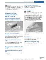
Page 163: ...orage compartments are located on the left and right sides Net for storage compartment Smaller objects can be stored in the net of right storage compartment Multi function hook WARNING Improper use of the multifunction hooks can lead to a danger of objects flying about during braking and evasive maneuvers There is risk of injuries and risk of property damage Only hang lightweight objects e g shopp...

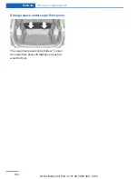
Page 164: ... under cargo floor panel The cargo floor panel can be folded To open the cargo floor panel lift slightly and push to ward the front Controls Storage compartments 164 Online Edition for Part no 01 40 2 964 303 VI 15 ...

Page 165: ...Storage compartments Controls 165 Online Edition for Part no 01 40 2 964 303 VI 15 ...

Page 166: ...Online Edition for Part no 01 40 2 964 303 VI 15 ...

Page 167: ...Driving tips This chapter provides you with information useful in dealing with specific driving and operating modes Online Edition for Part no 01 40 2 964 303 VI 15 ...

Page 168: ...ces when tires are brand new they achieve their full traction potential after a break in time Drive conservatively for the first 200 miles 300 km Brake system Brakes require an initial break in period of ap prox 300 miles 500 km to achieve optimal per formance between brake discs and brake pads Drive moderately during this break in pe riod Following part replacement The same break in procedures sh...

Page 169: ...with hot parts of the exhaust gas system these materials can ignite There is risk of injuries or risk of property damage Do not remove the heat shields installed and never apply undercoating to them Make sure that no combustible materials can come in contact with hot vehicle parts in driving opera tion idle or during parking Do not touch the hot exhaust system Mobile communication devices in the v...

Page 170: ...rake pedal ever so gently every few miles Ensure that this action does not endanger other traffic The heat generated in this process helps dry the brake discs and pads In this way braking efficiency will be available when you need it Hills WARNING Light but consistent brake pressure can lead to high temperatures brakes wearing out and possibly even brake failure There is risk of an accident Avoid ...

Page 171: ...sing the automatic climate control condensation water develops collecting under neath the vehicle These traces of water under the vehicle are normal Things to remember when driving Driving tips 171 Online Edition for Part no 01 40 2 964 303 VI 15 ...

Page 172: ...cts in the car s inte rior WARNING Unexpected movements of the backrest while driving may occur due to unintentional unlocking of the rear backrests by the loops There is risk of injuries Do not fasten any ob jects to the loops for unlocking the rear back rests Determining the load limit 1 Locate the following statement on your ve hicle s placard The combined weight of occupants and cargo should n...

Page 173: ...e cargo there are four lashing eyes in the cargo area Securing cargo WARNING Improperly stowed objects can shift and be thrown into the car s interior e g in the event of an accident or during braking and eva sive maneuvers Vehicle occupants can be hit and injured There is risk of injuries Stow and secure objects and cargo properly Smaller and lighter items secure with re taining straps or draw st...

Page 174: ...equate clearance is main tained for tilting and opening the glass sunroof Distribute the roof load uniformly The roof load should not extend past the loading area Always place the heaviest pieces on the bottom Secure the roof luggage firmly e g tie with ratchet straps Do not let objects project into the opening path of the tailgate Drive cautiously and avoid sudden acceler ation and braking maneuv...

Page 175: ...llowing use Attached parts on the vehicle impair the aero dynamics and increase the fuel consumption Close the windows and glass sunroof Driving with the glass sunroof and windows open results in increased air resistance and thereby reduces the range Tires General information Tires can affect fuel consumption in various ways e g tire size may influence fuel con sumption Check the tire inflation pr...

Page 176: ...educed Savings can begin within a few sec onds of switching off the engine In addition fuel consumption is also deter mined by other factors such as driving style road conditions maintenance or environmental factors Switch off any functions that are not currently needed Functions such as seat heating and the rear window defroster require a lot of energy and reduce the range especially in city and ...

Page 177: ...ilable when out side temperatures are very cold ECO PRO potential Shows potential savings with the current set tings in percentages Display in the instrument cluster ECO PRO bonus range An adjusted driving style helps you extend your driving range This may be displayed as the bonus range in the instrument cluster The bonus range is shown in the range display The bonus range is automatically reset ...

Page 178: ...celerator pedal The display switches to blue as soon as all conditions for fuel efficiency optimized driving are met Information The efficiency display and ECO PRO tips in the instrument cluster appear when the ECO PRO display is activated Activating driving style and ECO PRO tips 1 Settings 2 Instrument cluster 3 ECO PRO Info Driving tips Saving fuel 178 Online Edition for Part no 01 40 2 964 303...

Page 179: ...Saving fuel Driving tips 179 Online Edition for Part no 01 40 2 964 303 VI 15 ...

Page 180: ...Online Edition for Part no 01 40 2 964 303 VI 15 ...

Page 181: ... order to always ensure your mobility you will find important information on operating fluids wheels and tires maintenance and Roadside Assistance in the following Online Edition for Part no 01 40 2 964 303 VI 15 ...

Page 182: ...s are no longer ensured There is risk of property damage Re fuel promptly Fuel lid Opening 1 Briefly press the rear edge of the fuel filler flap 2 Turn the tank lid counterclockwise 3 Place the tank lid in the bracket attached to the fuel filler flap Closing 1 Fit the lid and turn it clockwise until you clearly hear a click 2 Close the fuel filler flap WARNING The retaining strap of the fuel cap b...

Page 183: ...d aggressive Overfill ing of the fuel tank can damage the fuel sys tem On contact with painted surfaces dam age may occur to these surfaces The environment is polluted There is risk of prop erty damage Avoid overfilling The fuel tank is full when the filler nozzle clicks off the first time Observe safety regulations posted at the gas station Refueling Mobility 183 Online Edition for Part no 01 40 ...

Page 184: ...ent Fuels that are marked on the gas pump as con taining metal must not be used CAUTION Even small amounts of wrong fuel or wrong fuel additives can damage the fuel sys tem and the engine Furthermore the catalytic converter is permanently damaged There is risk of property damage Do not refuel or add the following in the case of gasoline engines Leaded gasoline Metallic additives e g manganese or i...

Page 185: ... drivability start ing and stalling especially under certain envi ronmental conditions such as high ambient temperature and high altitude may occur If drivability problems are encountered we rec ommend switching to a high quality gasoline brand and a higher octane grade AKI num ber for a few tank fills To avoid harmful en gine deposits it is highly recommended to purchase gasoline from Top Tier re...

Page 186: ...ncreases along with the tire s temperature The tire inflation pressure speci fications relate to cold tires or tires with the ambient temperature Only check the tire inflation pressure when the tires are cold This means after driving no more than 1 25 miles 2 km or when the vehicle has been parked for at least 2 hours The displays of inflation devices may under read by up to 0 1 bar 2 psi For Flat...

Page 187: ... 36 2 5 36 Emergency wheel T 135 90 R 17 104 M Speed up to a max of 50 mph 80 km h 4 2 60 Tire inflation pressures at max speeds above 100 mph 160 km h WARNING In order to drive at maximum speeds in excess of 100 mph 160 km h please observe and if necessary adjust tire pressures for speeds exceeding 100 mph 160 km h from the relevant table on the following pages Other wise tire damage and accident...

Page 188: ...5 45 R 19 92 W RSC 3 0 44 3 0 44 Emergency wheel T 135 90 R 17 104 M Speed up to a max of 50 mph 80 km h 4 2 60 Tire identification marks Tire size 245 45 R 18 96 Y 245 nominal width in mm 45 aspect ratio in R radial tire code 18 rim diameter in inches 96 load rating not for ZR tires Y speed rating before the R on ZR tires Speed letter Q up to 100 mph 160 km h R up to 106 mph 170 km h S up to 112 ...

Page 189: ...t and concrete A tire marked C may have poor traction performance The traction grade assigned to this tire is based on straight ahead braking traction tests and does not include acceleration cornering hydroplaning or peak traction characteristics Temperature The temperature grades are A the highest B and C representing the tire s resistance to the generation of heat and its ability to dissipate he...

Page 190: ...e tires Indications of tire damage or other vehicle mal functions Unusual vibrations while driving Unusual handling such as a strong ten dency to pull to the left or right Damage can e g be caused by driving over curbs road damage or similar things WARNING Damaged tires can lose tire inflation pressure which can lead to loss of vehicle control There is risk of an accident If tire dam age is suspec...

Page 191: ...eated tires Winter tires Winter tires are recommended for operating on winter roads Although so called all season M S tires pro vide better winter traction than summer tires they do not provide the same level of perform ance as winter tires Maximum speed of winter tires If the maximum speed of the vehicle is higher than the permissible speed for the winter tires then a respective symbol is display...

Page 192: ... the tires which seals the damage from the inside The compressor can be used to check the tire inflation pressure Information Follow the instructions on using the Mobi lity System found on the compressor and sealant container Use of the Mobility System may be ineffec tive if the tire puncture measures approx 1 8 in 4 mm or more Contact a dealer s service center or an other qualified service center...

Page 193: ...Inflation pressure dial 5 Compressor 6 Connector cable for socket 7 Connection hose stowed in the bottom of the compressor Filling the tire with sealant 1 Shake the sealant container 2 Take the connection hose completely out of the compressor housing Do not kink the hose 3 Attach the connection hose to the connec tor of the sealing container ensuring that it engages audibly Wheels and tires Mobili...

Page 194: ...n pressure of approx 2 5 bar While the tire is being filled with sealant the tire inflation pressure may sporadically reach approx 5 bar Do not switch off the compres sor at this point If a tire inflation pressure of 2 bar is not reached 1 Switch off the compressor 2 Unscrew the filling hose from the wheel 3 Drive 33 ft 10 m forward and back to dis tribute the sealant in the tire 4 Inflate the tir...

Page 195: ...bar Increase pressure with the ignition turned on or the engine running switch on the compressor To reduce the pressure press the but ton on the compressor Continuing the trip Do not exceed the maximum permissible speed of 50 mph 80 km h Reinitialize the Flat Tire Monitor Reinitialize the Tire Pressure Monitor Replace the nonworking tire and the sealant container of the Mobility System as soon as ...

Page 196: ...s Do not initialize the Flat Tire Monitor after mounting snow chains as doing so may result in incorrect readings Do not initialize the Tire Pressure Monitor after mounting snow chains as doing so may result in incorrect readings When driving with snow chains briefly activate Dynamic Traction Control if needed Maximum speed with snow chains Do not exceed a speed of 30 mph 50 km h when using snow c...

Page 197: ...id 2 Vehicle identification number 3 Oil filler neck 4 Jump starting positive battery terminal 5 Jump starting negative battery terminal 6 Coolant reservoir Hood Information WARNING Improperly executed work in the engine compartment can damage components and lead to a safety risk There is risk of accidents or risk of property damage WARNING The engine compartment accommo dates moving components Ce...

Page 198: ...rrectly close the hood WARNING Body parts can be jammed on opening and closing the hood There is risk of injuries Make sure that the area of movement of the hood is clear during opening and closing Opening the hood 1 Pull lever arrow 1 Hood is unlocked 2 After the lever is released pull the lever again arrow 2 Hood can be opened Indicator warning lights When the hood is unlocked a Check Control me...

Page 199: ...s display Detailed measurement Electronic oil measurement Status display The concept The engine oil level is monitored electronically while driving and shown on the Control Dis play If the engine oil level reaches the minimum level a check control message is displayed Requirements A current measured value is available after ap prox 30 minutes of driving During a shorter trip the status of the last...

Page 200: ...uses engine damage There is risk of property damage Add engine oil within the next 125 miles 200 km CAUTION Too much engine oil can damage the en gine or the catalytic converter There is risk of property damage Do not add too much engine oil Have too much engine oil siphoned off by a dealer s service center or another qualified service center or repair shop WARNING Operating materials e g oils gre...

Page 201: ...ne oil types Add engine oils that meet the following oil rat ing standards Gasoline engine BMW Longlife 01 BMW Longlife 01 FE BMW Longlife 14 FE More information about suitable engine oil rat ings and viscosities of engine oils can be re quested from a dealer s service center or an other qualified service center or repair shop Alternative engine oil types If an engine oil suitable for continuous u...

Page 202: ... additives only Coolant consists of water and additives Not all commercially available additives are suitable for the vehicle Information about suit able additives is available from a dealer s serv ice center or another qualified service center or repair shop Coolant level Overview Depending on the engine installation the cool ant reservoir is located on the right side or the left side of the engi...

Page 203: ... coolant loss elimi nated as soon as possible Disposal Comply with the relevant environmen tal protection regulations when dispos ing of coolant and coolant additives Coolant Mobility 203 Online Edition for Part no 01 40 2 964 303 VI 15 ...

Page 204: ... Detailed information on service requirements refer to page 87 can be displayed on the Con trol Display Service data in the remote control Information on the required maintenance is continuously stored in the remote control The dealer s service center can read this data out and suggest an optimized maintenance scope for your vehicle Therefore hand the service advisor the remote control with which ...

Page 205: ...D socket on the driver s side for checking the primary components in the vehi cle s emissions Emissions The warning lamp lights up Emissions are deteriorating Have the vehicle checked as soon as possible The warning lamp flashes under certain circumstances This indicates that there is excessive mis firing in the engine Reduce the vehicle speed and have the system checked immediately otherwise seri...

Page 206: ...wn the wipers without the wiper blades installed Replacing the front wiper blades 1 To change the wiper blades fold up refer to page 76 the wiper arms 2 Fold up and hold the wiper arm firmly 3 Press button arrow 1 and pull out the wiper blade 4 Insert the new wiper blade in reverse order of removal until it locks in place 5 Fold down the wipers CAUTION Folded away wipers can be jammed when the hoo...

Page 207: ... for an extended period of time Do not remove the LED covers Headlight glass Condensation can form on the inside of the ex ternal lights in cool or humid weather When driving with the lights switched on the con densation evaporates after a short time The headlight glass does not need to be changed If despite driving with the lights switched on increasing humidity forms e g water droplets in the la...

Page 208: ...removal Low beams 55 watt bulb H7LL 1 Access to the low beams on the right side unhook and fold away the filler neck for the wiper fluid with the screwdriver from the onboard vehicle tool kit 2 Turn the cover counterclockwise and re move 3 Pull the bulb holder directly to the rear ar row 1 and remove 4 Remove the bulb from the bulb holder 5 Install the new bulb with bulb holder in re verse order o...

Page 209: ... lights 1 Parking lights daytime running lights 2 Side marker lights 3 Turn signal 4 Low beams high beams headlight flasher 5 Corner illuminating lights Front lights The following lights feature LED technology High beams Parking lights daytime running lights Low beams Corner illuminating lights Contact a dealer s service center or another qualified service center or repair shop in the event of a m...

Page 210: ...instructions refer to page 206 35 watt bulb H8 1 Insert the screwdriver from the onboard vehicle tool kit with the flat side on the clip arrow 1 2 Turn the screwdriver by 90 arrow 2 3 Remove the front fog lamp toward the front 4 Detach the connector 5 Turn the bulb bracket and remove it 6 Remove the bulb and replace it 7 Proceed in reverse order to insert the front fog lamp Note the guide rails in...

Page 211: ...rvice center or another qualified service center or repair shop in the event of a malfunction Bulb replacement exterior tail lights General information Follow general instructions refer to page 206 Turn signal 21 watt bulb P21WLL Outer brake lamp 21 watt bulb P21WLL Removing the exterior tail lamp 1 Open the tailgate 2 Remove the fastening using the screw driver from the onboard vehicle tool kit a...

Page 212: ... bolt 3 Press on the tail lights until flush and tighten both of the nuts Mount the cover Lights in the tailgate Vehicles with halogen headlights Follow general instructions refer to page 206 Reversing lamp 21 watt bulb P21WLL Inner brake lamp 21 watt bulb H21WLL Tail light 5 watt bulb P21WLL Vehicles featuring LED headlights Follow general instructions refer to page 206 Reversing lamp 21 watt bul...

Page 213: ...ice center or another qualified service center or repair shop Jacking points for the vehicle jack The jacking points for the vehicle jack are lo cated at the positions shown Emergency wheel Safety measures Park the vehicle as far away as possible from passing traffic and on solid ground Switch on the hazard warning system Set the parking brake and engage lever in position P P Have all vehicle occu...

Page 214: ...ally beneath the vehicle jacking point with the entire surface on the ground 2 Insert the vehicle jack head in the rectan gular recess of the jacking point for crank ing it up 3 Crank it up until the wheel in question lifts off of the ground Wheel mounting Mount one emergency wheel only 1 Unscrew the wheel lug bolts and remove the wheel 2 Put the new wheel or emergency wheel on and screw in at lea...

Page 215: ...s service center or another qualified service center or repair shop to ensure that all comfort features are fully available and that any Check Control messages of these comfort fea tures are no longer displayed Charging the battery General information Make sure that the battery is always suffi ciently charged to guarantee that the battery remains usable for its full service life The battery may ne...

Page 216: ... not tip over during transport Fuses Information WARNING Incorrect and repaired fuses can overload electrical lines and components There is risk of fire Never attempt to repair a blown fuse and do not replace a nonworking fuse with a substitute of another color or amperage rat ing Plastic tweezers and information on the fuse types and locations are stored in the fuse box in the glove compartment I...

Page 217: ... under unfavorable con ditions Overview SOS button in the roofliner Requirements The SIM card integrated in the vehicle has been activated The radio ready state is switched on The Assist system is functional Initiating an Emergency Request 1 Press the cover briefly to open it 2 Press the SOS button until the LED at the button lights up green The LED lights up green an Emergency Request was initiat...

Page 218: ...tems promptly Storage The first aid kit is located in the cargo area on the left in the storage compartment Jump starting General information If the battery is discharged the engine can be started using the battery of another vehicle and two jumper cables Only use jumper ca bles with fully insulated clamp handles Information DANGER Contact with live components can lead to an electric shock There i...

Page 219: ...onding engine or body ground of assisting vehicle 5 Attach the second terminal clamp to the negative terminal of the battery or to the corresponding engine or body ground of the vehicle to be started Starting the engine Never use spray fluids to start the engine 1 Start the engine of the assisting vehicle and let it run for several minutes at an in creased idle speed 2 Start the engine of the vehi...

Page 220: ...bed sur face only CAUTION When lifting the vehicle by the tow fitting or body and chassis parts damage can occur on vehicle parts There is risk of property dam age Lift vehicle using suitable means Use tow fitting located in the front only for po sitioning the vehicle Towing other vehicles Information WARNING If the approved gross vehicle weight of the towing vehicle is lighter than the vehicle to...

Page 221: ... the onboard vehicle tool kit refer to page 206 are together in the cargo area Information CAUTION If the tow fitting is not used as intended there can be damage to the vehicle or to the tow fitting There is risk of property damage Observe the notes on using the tow fitting Use of the tow fitting Use only the tow fitting provided with the vehicle and screw it all the way in Use the tow fitting for...

Page 222: ...d temperature Maximum temperature 140 60 Minimum distance from sensors cameras seals 12 in 30 cm Minimum distance from glass sunroof 31 5 inches 80 cm Automatic car washes Information Give preference to cloth car washes or those that use soft brushes in order to avoid paint damage Make sure that the wheels and tires are not damaged by the transport mechanisms Fold in the exterior mirrors otherwise...

Page 223: ... instructions on the container Vehicle paint Regular care contributes to driving safety and value retention Environmental influences in areas with elevated air pollution or natural con taminants such as tree resin or pollen can af fect the vehicle s paintwork Tailor the fre quency and extent of your car care to these influences Aggressive substances such as spilled fuel oil grease or bird dropping...

Page 224: ...der to avoid damage or noises Fine wood parts Clean fine wood facing and fine wood compo nents only with a moist rag Then dry with a soft cloth Plastic components These include Imitation leather surfaces Roofliner Lamp lenses Instrument cluster cover Matt black spray coated components Painted parts in the interior Clean with a microfiber cloth Dampen cloth lightly with water Do not soak the roofli...

Page 225: ...t Displays Screens protective glass of the Head up Display CAUTION Chemical cleansers moisture or fluids of any kind can damage the surface of displays and screens There is risk of property damage Clean with a clean antistatic microfiber cloth CAUTION The surface of displays can be damaged with improper cleaning There is risk of prop erty damage Avoid pressure that is too high and do not use any s...

Page 226: ...Online Edition for Part no 01 40 2 964 303 VI 15 ...

Page 227: ...Reference This chapter contains the technical data and an index that will quickly take you to the information you need Online Edition for Part no 01 40 2 964 303 VI 15 ...

Page 228: ...t method Detailed values can be found in the approval documents on labels on the vehicle or can be obtained from a dealer s service center or another qualified service cen ter or repair shop The information in the vehicle documents al ways has priority Dimensions The dimensions can vary depending on the model version equipment or country specific measurement method The specified heights do not tak...

Page 229: ... to page 184 Technical data Reference 229 Online Edition for Part no 01 40 2 964 303 VI 15 xDrive28i Approved gross vehicle weight lbs kg Load lbs kg Approved front axle load lbs kg Approved rear axle load lbs kg Approved roof load capacity lbs kg Cargo area capacity cu ft l 4 720 2 141 900 408 2 470 1 120 2 375 1 077 165 75 27 1 58 7 505 1 550 ...

Page 230: ...3 VI 15 Active pedestrian protection system Opposite to the description in this Owner s Manual the active pedestrian protection sys tem is only deployed at speeds between ap prox 30 km h approx 18 mph and 55 km h 34 mph Speed limit detection Opposite to the description in this Owner s Manual the display cannot be switched on off via iDrive ...

Page 231: ...Appendix Reference 231 Online Edition for Part no 01 40 2 964 303 VI 15 ...

Page 232: ...rrival time 91 Ashtray 155 Assistance when driving off 125 Assist system see Intelligent Safety 111 Attentiveness assistant 118 AUTO intensity 147 Automatic car wash 222 Automatic climate con trol 146 Automatic cruise control with Stop Go 126 Automatic Curb Monitor 61 Automatic deactivation Front seat passenger air bags 104 Automatic headlight con trol 98 Automatic locking 46 Automatic recirculate...

Page 233: ...ildren transporting safely 64 Child restraint fixing sys tem 64 Child restraint fixing system LATCH 66 Child restraint fixing systems mounting 65 Child safety locks 67 Child seat mounting 65 Child seats 64 Chrome parts care 224 Cigarette lighter 155 Cleaning displays 225 Climate control 144 146 Clock 86 Closing opening via door lock 39 Closing opening with remote control 37 Closing the tailgate wi...

Page 234: ...ynamic Stability Con trol 120 DTC Dynamic Traction Con trol 121 Dynamic Damping Con trol 123 Dynamic Stability Control DSC 120 Dynamic Traction Control DTC 121 E ECO PRO 176 ECO PRO bonus range 177 ECO PRO display 176 ECO PRO driving mode 176 ECO PRO mode 176 ECO PRO program driving dynamics 124 Electronic displays instru ment cluster 81 Electronic oil measure ment 199 Electronic Stability Program...

Page 235: ...ntrol 151 Gasoline 184 Gear change Steptronic transmission 77 Gear shift indicator 88 General driving notes 169 Glare shield 155 Glass sunroof refer to Panor amic glass sunroof 49 Glove compartment 160 Gross vehicle weight ap proved 229 H Halogen headlights 207 Handbrake see Parking brake 72 Hand held transmitter alter nating code 152 Hazard warning flashers 217 HDC Hill Descent Con trol 122 Head ...

Page 236: ...mp starting 218 K Key remote control 34 Keyless Go see Comfort Ac cess 43 Key Memory see Personal Profile 35 Kickdown Steptronic trans mission 77 Knee airbag 103 L Label on recommended tires 191 Lamp replacement 206 Lamp replacement front 207 Lamp replacement rear 211 Lane departure warning 117 Lane margin warning 117 Language on Control Dis play 94 Lashing eyes securing cargo 173 LATCH child rest...

Page 237: ...ee OBD Onboard Di agnosis 205 Obstacle marking rearview camera 139 Octane rating see Recom mended fuel grade 184 Odometer 86 Office 6 Offroad trips 168 Oil 199 Oil adding 200 Oil additives 201 Oil change 201 Oil change interval service requirements 87 Oil filler neck 200 Oil types alternative 201 Oil types suitable 201 Old batteries disposal 216 On board computer 90 On board computer refer to On b...

Page 238: ...straps securing cargo 173 Retreaded tires 191 Roadside parking lights 98 RON recommended fuel grade 184 Roofliner 17 Roof load capacity 229 Roof mounted luggage rack 173 Rope for tow starting towing 220 RSC Run Flat System Com ponent see Run flat tires 192 Rubber components care 224 Run flat tires 192 S Safe braking 170 Safety belt reminder for driv er s seat and front passen ger seat 57 Safety be...

Page 239: ...Dynamic Driv ing 124 Switch on times parked car ventilation 149 Switch refer to Cockpit 14 Symbols 6 Symbols in the status field 23 SYNC program automatic cli mate control 148 T Tachometer 86 Tailgate automatic 41 Tailgate closing 41 Tailgate closing with no touch activation 44 Tailgate opening 40 Tailgate opening with no touch activation 44 Tailgate via remote con trol 38 Tail lights 211 Technica...

Page 240: ... to Parked car ventilation 149 VIN see vehicle identification number 10 Voice activation system 26 W Warning and indicator lamps see Check Control 82 Warning displays see Check Control 82 Warning messages see Check Control 82 Warning triangle 218 Warranty 7 Washer fluid 76 Washer nozzles wind shield 76 Washer system 74 Washing vehicle 222 Water on roads 169 Weights 229 Welcome lamps during un lock...

Page 241: ......

Page 242: ...More about BMW bmwusa com The Ultimate Driving Machine 01 40 2 964 303 ue BL2964303001 Online Edition for Part no 01 40 2 964 303 VI 15 ...

Reviews: