


14
4.
If the phone identifies/finds a device select it and follow the indicated steps to complete the pairing
process.
5.
Once the phone is successfully paired to the device cycle the ignition switch off and back on and the
devices should wirelessly connect within 30 seconds. When the connection is established the
phone will display a connection symbol.
The following steps are an example of the pairing procedure that must be initiated to pair the Sony
Ericsson T68i phone to the ULF Control Module.
1.
Press the menu button.
2.
Select “Connect”.
3.
Select option 3: “Bluetooth”.
4.
Select option 4: “Options”.
5.
Select option 1: “Operation mode” and set to “On” or “Automatic”.
6.
Go back one step by pressing the red phone button.
7.
Select option 3: “Discover”.
•
Mobile Phone display shows ‘Searching’
8.
Select “BMW ……” in upcoming list.
9.
Select option 1: “Add to paired”
10.
Enter password (= ULF passkey) located on ULF Control Module in the rear of the vehicle or on the
Passkey Reference Card.
•
Mobile Phone display shows ‘BMW …… Pairing’
•
Mobile Phone display shows ‘Pairing Successful’
•
Board Monitor display shows ‘Pairing succeeded’ for 3 seconds
11.
Enter device name.
12.
Mobile Phone display shows “Added to paired devices”.
13.
Quit menu by pressing the red phone/NO button for several seconds.
14.
Once the phone is successfully paired to the
device cycle the ignition switch off and back
on.
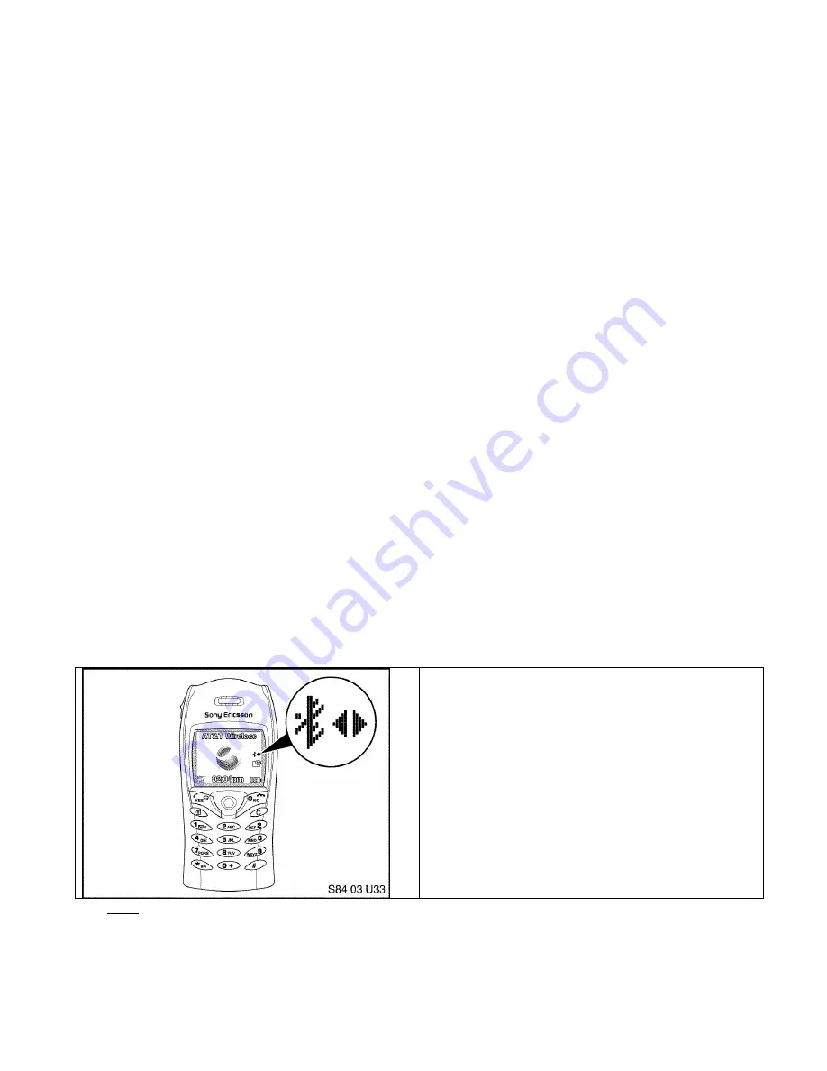
15.
The devices should wirelessly connect within
30 seconds. The connection is established
when the phone displays the symbols
indicated, on the right side of the screen.
Note: Shortly after turning on the ignition and the Bluetooth
TM
connection is identified, the phone
may display a message asking if the connection should be established/accepted. The connection
authorization request will always occur unless the setting on the phone is modified to allow
automatic connection every time, please refer to the user’s manual of the phone to determine how to
change this setting.