# 12783 Aquila
copyright © 2008 BMI
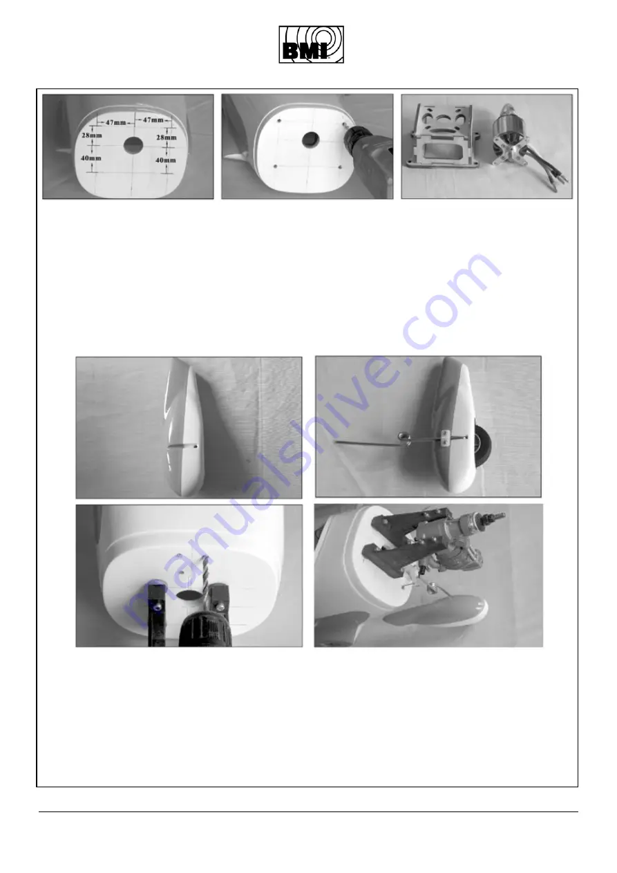
1. Drill four holes in the corners of the
pattern and attach the motor mount to
the fuselage with 4 screws.
2. Attach the motor to the mount with
four screws.
3. Pay attention that the distance from
the firewewall to the front motorwash
-
er is 145 mm.
4. For an optimal cooling it is recom
-
mended to install the ESC inside the
motor mount.
1. Forez quatre trous commme indi
-
qué et fixez le support moteur au fu
-
selage.
2. Fixez le moteur sur son bâti-mo
-
teur.
3. La distance entre le plateau d’hélice
et le couple pare-feu est de 145 mm.
4. Pour un meilleur refroidissement
nous vous conseillons d’installer le
controleur à l’intérieur du bâti-moteur.
1. Bohren Sie 4 Löcher in die Ecken der
Sjablone und befestigen Sie den Mo
-
torträger mit 4 Schrauben und Muttern
an den Rumpf.
2. Befestigen Sie den Motor an den
Motorträger mit 4 Schrauben.
3. Vorsicht: der Abstand des Motor
-
spants zur Luftschraube muss 145mm
sein.
4. Für eine optimale Kühlung sollte
der Motorregler am besten in den Mo
-
torträger montiert werden.
1. Boor 4 gaten in de hoeken van het
sjabloon en bevestig de motorsteun
met 4 schroeven en 4 moeren aan de
romp.
2. Bevestig de motor aan de motor
-
steun met 4 schroeven.
3. Let op: de afstand van de vuurplaat
tot de schroefplaat dient 145 mm te
bedragen.
4. Voor optimale koeling kan de mo
-
torregelaar best in de motorsteun ge
-
monteerd worden.
1. Drill a hole at the bottom of the
molded groove in the wheel pant so
that the axle can pass through.
2. Install the wheel by inserting the
nose wheel axle trough the wheel
pant. Make sure the wheel can move
freely.
3. Fix the axle mounting the nylon
plate with two screws.
4. Drill four holes to attach the nose
gear bearing. Insert the axle into the
nose gear bearing.
5. Drill one hole to allow the push
-
rod for the nose gear wheel to pass
through.
1. Forez un trou afin de faire passer la
commande de gaz.
2. Installez la roue avant et son axe
dans le cache-roue et veillez que la
roue tourne librement.
3. Fixez le cache-roue au moyen du
cavalier et 2 vis.
4. Forez 4 trous pour fixer le bloc de
base du train avant et inserez-y la
jambe.
5. Forez un trou dans l’axe pour la
commande de la direction du train
avant.
1.Loch bohren wie abgebildet
2.Das Rad anschrauben und darauf
achten, dass sich das Rad frei bewe
-
gen kann.
3.Bohren Sie 4 Löcher um den Halter
des Landegestells zu befestigen. An
-
schliessend die Achse durch den Halter
schieben.
4. Eine Öffnung machen wodurch die
Steuerung des vordersten Rads er
-
möglicht wird.
1. Boor een gaatje onderaan de sleuf
zodat de as er door kan.
2. Schroef het wiel aan de wielverkled
-
ing en zorg ervoor dat het wiel vrij kan
bewegen.
3. Boor 4 gaatjes om de houder van
het landingsgestel te bevestigen. Steek
vervolgens de as door de houder.
4. Maak een opening waardoor de aan
-
sturing van het voorste landingswiel
kan gedaan worden.
5.10 Installation of the nose landing gear / Installation de la roue de nez
Bugrad montieren / Installatie van het neuswiel


